ISSN ONLINE(2319-8753)PRINT(2347-6710)
ISSN ONLINE(2319-8753)PRINT(2347-6710)
| R. Naga Venkatesh Sankar Dept of Information Technology, SSN College of Engineering , Kalavakkam, Chennai, India. |
| Related article at Pubmed, Scholar Google |
Visit for more related articles at International Journal of Innovative Research in Science, Engineering and Technology
Some applications require location information of objects in an indoor environment. However, the human entry to the indoors (of a building) may not always be desirable as the knowledge of (safe/unsafe) objects inside a building is known only after entry.In this paper, we aim to provide a sketch of the indoor profile by using mobile sensors like Kinect sensor and optical mouse.
Keywords |
| indoor profile, Kinect sensor |
INTRODUCTION |
| Indoor GPS signal reception is not accurate and sometimes not feasible because the signal cannot penetrate through all the building and indoor structures and the reception is not good and the location can be only estimated in terms of some meters. Currently there is no defined standard for Indoor Positioning System even for a known environment and known object, where in most cases the indoor environment is equipped with several signal transmitters or tags, receivers or readers, RADAR[1]and WIFI[2]which is used to track or locate the position of the items within the environment and there may be unsafe environment for the humans to enter inside like, Military fields, Hazardous gas and radiation region etc. |
| Identifying the object location in the indoor is necessary to understand the internal structure which is achieved by means of remote sensing[3], so a robot is sent inside to identify the indoor structure and the location of obstacles, using mobile sensors. This information is collected periodically and transmitted by the robot application over the network and monitored live as a digital sketch by an application in a remote system. |
| Instead observing the environment using any standard RGB camera and streaming as a video signal, depth information is also acquired for better understanding of the indoor structures. Video streaming may not be possible under all circumstances. First it is highly bandwidth consuming system. Second the safety of the system is questionable. Transmitting still images at regular intervals solves these issues. But the images in general are overlapped and needs to be stitched to get the complete picture of a place. In this work a dynamic (i.e. moving remote sensor) is sent inside the place of interest. The sensor will be capturing images at regular time intervals and will transmit the image to remote console. Along with the image the depth information is also sent. Using these two informations the indoor profile will be created. |
| A.Kinect Sensor[4] |
| The Kinect for Windows Sensor is a physical device as shown in Fig.1 that, when used with a computer and the accompanying Kinect for Windows software developer kit, provides the foundation we need to create interactive applications[5] that recognize peoples' natural movements, gestures, and voice commands. End users use the sensor, with its built-in RGB camera, infrared emitter, depth sensor, and microphone array as shown in Fig. 2, to run Kinect for Windows touch-free applications[6]. |
| ïÃâ÷ An RGB camera that stores three-channel data in a 1280 x 960 resolution at 12 frames per second, or a 640 x 480 resolution at 30 frames per second. This makes capturing a color image or video possible. |
| ïÃâ÷ An infrared (IR) emitter and an IR depth sensor. The emitter emits infrared light beams and the depth sensor reads the IR beams reflected back to the sensor. The reflected beams are converted into depth information measuring the distance between an object and the sensor. This makes capturing a depth image possible. |
| ïÃâ÷ A multi-array microphone that contains four microphones for capturing sound. Because there are four microphones, it is possible to record audio from a specific direction, as well as find the location of the sound source and the direction of the audio wave. |
| ïÃâ÷ A three-axis accelerometer configured for a 2G range, where G is the acceleration due to gravity. It is possible to use the accelerometer to determine the current orientation of the sensor. |
| The Kinect Services support the following features: |
| ïÃâ÷ Depth image including Player Index |
| ïÃâ÷ Depth image including Player Index |
| ïÃâ÷ Tilt |
| ïÃâ÷ Microphone Array |
| ïÃâ÷ Skeleton Tracking |
 |
| We can specify the resolution of the Depth and RGB cameras independently via a config file, as well as the depth camera mode. The config file also specifies whether we want skeleton tracking to be performed or not. If we do not use the skeleton data, we should not track it because there is a performance overhead. We cannot turn skeleton tracking on once the service is running, so it must be selected in the config file. |
| The Kinect depth sensor range is: minimum 800mm and maximum 4000mm. The Kinect for Windows Hardware can however be switched to Near Mode which provides a range of 500mm to 3000mm instead of the Default range. If we are using an Xbox Kinect with the Kinect for Windows SDK then Near Mode is not supported. |
| 1) Limitations:The Kinect uses Infrared so it can see through glass. Therefore it cannot be used reliably for obstacle avoidance if you have glass doors. Also because it uses IR, the Kinect will not work in direct sunlight. |
B. Kinect for Windows Software Development Kit (SDK) |
| The Kinect for Windows SDK[7] and toolkit contain drivers, tools, APIs, device interfaces, and code samples to simplify development of applications for commercial deployment. The Kinect for Windows SDK exposes an array of sensor data and provides developers with effective tools to optimize their use of that data: developers can access extended depth data and the sensor’s IR emitter, and can control the custom color camera settings. The Kinect for Windows SDK supports up to four sensors on one computer, and can be used on any virtual machine whose native operating system supports running Windows. |
| The Kinect for Windows SDK enables you to use C++, C#, or Visual Basic to create applications and experiences that support gesture and voice recognition by using the Kinect for Windows sensor and a computer or embedded device. The Developer Toolkit contains additional resources, sample applications with full source code, Kinect Studio, and other resources to simplify and speed up application development. |
II.PROPOSED WORK |
B. Design Overview |
| The proposed method consists of client side robot and remote side console. |
| The mobile sensors like optical mouse and Kinect sensor are connected to the data acquisition device, a laptop at the client robot as shown in Fig. 3, which is operated by the data acquisition application installed in it. The client robot app thereby transmits the collected data periodically over the ad-hoc network connected with the remote console, for every 5ms to 50ms or depending upon the availability of new data based on the movement of the robot. |
| The remote console runs a service and an application as shown in Fig. 4, for sketching the profiling data. The mobile sensor data transmitted periodically by the client robot is collected by the service. The application installed in the remote console request the service for the data periodically for every 5ms and draws the robot path using the location information from the optical mouse’s data and the depth information of the indoor from the Kinect sensor’s data. |
 |
 |
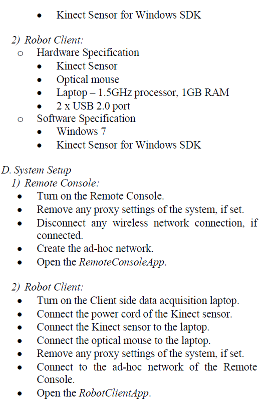
| On completing the above steps on both the client robot and remote console, the setup is complete and ready for automatic indoor profiling. The whole client setup is moved over a plane surface in such a way that the optical mouse is made to touch the surface constantly and the Kinect sensor is pointed in the appropriate direction and angle, where the client application as shown in Fig. 5 will transmit the data and its thereby viewed at the remote console application as shown in Fig. 6. |
| E. Implementation |
| 1) Robot Client:The RobotClientApp is created as a Windows Presentation Foundation[8] application with .NET 4.5 version and C# language. Major components required are |
| ïÃâ÷ System.Windows.Forms.Cursor |
| ïÃâ÷ System.Windows.Threading.DispatcherTimer |
| ïÃâ÷ Microsoft.Kinect[9] |
| KinectSensorChooser property is used to activate the connected Kinect Sensor and the DepthStream is enabled at 320x240 resolution and at 30 Frames per second. And for a better understanding, the variations in the depth values are represented with the color values. For the depth value less than 0.9m, blue color is used, for the depth value between 0.9m and 2.0m, green color is used and for the depth value greater than 2.0m, red color is used to represent. |
| Position of the mouse cursor is read whenever there is a change in its value and stored temporarily in a variable. |
| Since the movement of the mouse cursor cannot be measured beyond the resolution of the display screen, the mouse position is reset to the center of the screen when it reaches the boundary of the screen, by appending the position value. X and Y value can be obtained by accessing the Position.X and Position.Yproperty respectively. |
| Both the depth information and the cursor position information are transmitted by the dispatch timer to the web reference service at the remote console. When both the robot client and the remote console are connected in ad-hoc, the web reference can be configured by the IP address. |
| 2) Remote Console:The RobotClientApp is created as a Windows Presentation Foundation application with .NET 4.5 version and C# language. Major components required are |
| ïÃâ÷ System.Windows.Controls |
| ïÃâ÷ Microsoft.Kinect |
| Canvas control is used to map the position information obtained from the optical mouse position. The polyline method is used to add the position points to the canvas element, thereby the contour of the client robot path is achieved. |
| The depth information is represented with different color profile and it is viewed in an Image control. Further new depth data received will be updated in the Image control. |
| Both the position and the depth information is periodically pulled from the web reference service running within the remote system. |
 |
III.CONCLUSION AND FUTURE WORK |
| In this paper, client side robot application collects the relative location information from the optical mouse sensor and depth information from the Kinect sensor and transmit over the ad-hoc network to the service and application in remote console, which plots the data information. In future work, a single sketch of the indoor environment will be obtained using image stitching methods by feature extraction [10][11] and blending of several information acquired, and thereby the objects may be identified and its location or distance can be measured accordingly. |
References |
|