ISSN ONLINE(2320-9801) PRINT (2320-9798)
ISSN ONLINE(2320-9801) PRINT (2320-9798)
Ms. Samiksha P. Nate1, Ms. Shweta B. Bansude2, Ms. Anuja M. Bhosale3, Prof. A. S. Shitole4
|
| Related article at Pubmed, Scholar Google |
Visit for more related articles at International Journal of Innovative Research in Computer and Communication Engineering
With the advent of industrialization and increasing luxurious lifestyle, transportation has become the major part of our lives. Today large numbers of vehicles run during day and night time. Nowadays the number of accidents is increasing due to negligence of the driver. Negligence such as attending phone calls, lack of awareness, exhaustion due to prolong driving, etc. The existing system includes the speed control, when the speed of the front vehicle reduces, resulting in deceleration of the vehicle behind. This project covers overtaking of the vehicles without manual efforts. Hence, the sensors present on the vehicle will sense the neighbouring obstacles. When the obstacle is sensed, the overtaking mechanism will be triggered; the obstacle may be the vehicles on any side running on the road or anything. This concept will establish automation and ease in driving.
Keywords |
| overtaking, automatic, windscreen, wiper |
INTRODUCTION |
| Every day with morning coffee, we read the newspaper, which is unfortunately full of stories of accidents that occurred the previous day or if they were very major than those which occurred a couple of days ago or sometimes even weeks ago. And the sad part about this is that we read or hear such news on television almost every day. We definitely recall being extremely disturbed due to these pieces of news and saying, “God, when is this massacre going to stop?” |
| More news about the accidents pop up which took place on highways and we also know the reason for it. The speed of vehicles on the highways it is. As per the rule, each vehicle that travels on the highway has the speed of more than 50kmph, which makes the driver difficult to stay aware of every little thing happening around him and apply instant brakes when some vehicle is approaching towards it in extreme speed or he himself is going to collide with some other vehicle or any obstacle in great speed. |
| Because of the high speed of vehicles on the highway, it becomes nearly impossible for the driver to make quick decisions of applying brakes or even overtaking the obstacle in front of it. This occurs because the driver is practically unable to maintain constant and proper control over his vehicle due to the speed of his and other vehicles. Sometimes the driver has been driving for all night which makes him feel tired as a result of which he may take his mind off of the obstacles or when he is talking on the phone; he has to attend the call but can‟t even stop because he may be in a hurry. This can also take his mind off from being aware. A moment‟s distraction can cause him his life! What more adds fuel to the situations is the presence of rain. Imagine the condition of the driver; he needs to stay aware of everything going around him, he needs to be paranoid and have one foot, ready, on the brakes and he also needs to activate the wipers if it is raining. What if we say we could reduce a little pain of the driver by doing some of the things for him? Wouldn‟t that be effortless for the driver? Our system takes care of it. |
II. MATERIALS AND METHODS |
 |
| The system constitutes of three working components: a remote control, a vehicle and an automatic wiper system installed on the vehicle. |
A. Working of the Remote Control |
 |
| The keypad of the Remote Control will have four buttons, Left, Right, Forward and Backward and it wi ll hold two major components: an Encoder and an RF Transmitter. |
| HT-12E is an encoder that converts incoming digital signals to pulses. It will be configured for receiving input, and it will sense which key is pressed. It will encode 12 bits of information and serially transmit the information by receiving a Transmit Enable (TE) signal to an RF Transmitter. The RF Module which operates at Radio Frequency comprises of a pair of RF Transmitter and RF Receiver. In the RF system, the digital data is represented as variations in the amplitude of carrier wave by using the modulation known as Amplitude Shift Keying (ASK). The RF Transmitter in the remote control will transmit the converted analog signals to the RF Receiver, which will be located on the vehicle. Its range is about 100 meters and the transmitter/receiver (Tx/Rx) pair operates at a frequency of 433 MHz. |
B. Working of the Vehicle |
 |
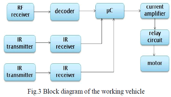
| The vehicle will have the following major components: an RF Receiver, Decoder, 8051 Microcontroller, Current amplifier, Relay, Motor, IR Transmitter and IR receiver. |
| The RF Receiver will receive the analog signal that were being transmitted by the remote control and convert them back to digital signals and pass them on to the HT-12F, a decoder. A decoder is a device that undoes the encoding so that the original information can be retrieved. It converts incoming pulses to digits. HT-12F receives the data transmitted by HT-12E and interprets all 12 bits of code period as address and if the entire address code received is matched, the valid transmission (VT) output goes high. |
| Here we are using 89S52 Microcontroller from the 8051 family. The microcontroller GPIO pins are configured for receiving input will receive digital signals from the decoder. Depending upon the controls pressed on the remote control, it will generate signals for the motor. Motor is responsible to move vehicle. Since the signals generated by the microcontroller are very weak and cannot be accepted by the motor, those signals are first given to the Current Amplifier, ULN 2003A which amplifies the current so as the motor can handle it sufficiently and then passes the amplified signals to the Relay. Relay is an electrically operated switch. When current flows through its coil a magnetic field causes the internal paddle to move positions. Relays are interfaced to motors. Motor is a widely used device that translates electric pulses into mechanical movements. The signals coming from relay i.e. switch on/off enables the motor to move in clockwise or counter clockwise direction. Wheels are attached to the shaft of the motor that finally makes the vehicle move as per the instructions that come from the remote control. Here the DC |
| Motors are used, but stepper motors can also be used for greater precision. The DC motor operates at frequency of 30RPM. |
| Now, while all the above process is in progress, something more will be constantly working in the vehicle. The obstacle detection components will be constantly running. |
| The IR LED mounted on the IR Transmitter circuit will constantly keep emitting the Infra Red Radiations so as to detect obstacles in its range. The Timer IC LM555 will act as a frequency generator for IR LED. The range of IR LED is set to 30cms. |
| Once the IR beam collides with an obstacle, it will be reflected back and will be sensed by TSOP 1738, mounted on IR Receiver circuit of the vehicle. Its output is provided as an input to IC LM311. The LM311 acts as a comparator and amplifier as well. Its output is further provided to 89S52 microcontroller. In the presence of obstacle, the microcontroller will receive a low signal and the Overtaking Mechanism will be triggered and a decision will be made about whether to overtake the obstacle or just to slow down the vehicle depending on the position of the obstacles. |
| If there are no obstacles, the microcontroller will receive a high signal allowing it to take the decision of continuing with its previous work. |
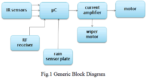
C. Working of Automatic Wiper |
 |
| Meanwhile, a rain plate is located on the windshield of the vehicle so as to detect moisture i.e. rain or snow. The moment raindrops or snowflakes touch the rain plate, it provides conducting path between two tracks. This causes a high voltage to be detected on the pin, and therefore the microcontroller 89S52 drives the motor for wiper movement. A separate DC Motor is installed on the vehicle to move the wiper. Since the signals generated by the microcontroller are weak to be accepted by the motor, they are first given to the Current Amplifier, ULN 2003A which amplifies them then passes it to the Relay. The signals coming from relay enables the motor to move in clockwise and counter clockwise motion. The DC motor operates at frequency of 30RPM. |
| When the accumulated moisture on the windscreen dries off, the conducting path between the tracks on the rain plate is broken. This causes a low voltage to be detected on the microcontroller‟s pin and allows it to take the decision of halting the motion of the DC motor by providing ground path. |
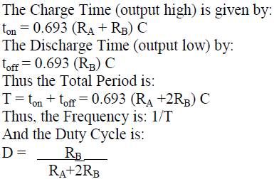
| Here the Astable Operation has been used as an application of IC LM555 in the IR transmitter. IR transmitter circuit drives the IR LED to transmit the IR radiations. The circuit triggers itself and free runs as a multivibrator. The external capacitor charges through (RA + RB) and discharges through RB. Thus the duty cycle is precisely set by the ratio of these two resistors. In this mode of operation, the capacitor charges and discharges between 1/3 VCC and 2/3 VCC. The Frequency generated should be 38 KHz. Following are the calculations needed to get the desired frequency: |
 |
RESULTS |
| Once the model of the vehicle having Automatic Overtaking System is accomplished, the following test cases should be satisfied by the system. |
| The RF Transmitter and Receiver should work as mentioned below: |
| 1. When the „Front‟ key is pressed on the remote, the vehicle should move in front direction. |
| 2. When the „Back‟ key is pressed on the remote, the vehicle should move in reverse direction. |
| 3. When the „Left‟ key is pressed on the remote, the vehicle should move in the left direction. |
| 4. When the „Right‟ key is pressed on the remote, the vehicle should move in the right direction. |
| We assume that the IR sensors will be fitted on the three sides of the vehicle: left, right and in the front direction. Following are the cases of presence of the obstacle and the system‟s behaviour in response to it: |
| 1. If any obstacle is present in the front of our vehicle, our vehicle should successfully overtake it from the right side. |
| 2. If an obstacle is present on the left of our vehicle, our vehicle should just slightly swerve towards its right. |
| 3. If an obstacle is present on the right of our vehicle, our vehicle should just slightly swerve towards its left. |
| 4. If the obstacles are present in the left and right side of the vehicle, our vehicle should simply propagate forward. |
| 5. If obstacles are present in the front and in the left of our vehicle, our vehicle should successfully overtake them from the right side only. |
| If obstacles are present in the front and in the right of the vehicle, our vehicle should simply slow down or stop as it is outlawed to overtake from the left in India. |
| 7. If there are obstacles in the front, left and right, our vehicle does not possess any other option than to slow down or continue with their speed. |
IV. CONCLUSIONS |
| The existing system for manual overtaking needs the complete awareness of the driver, which is irrespective of the travelling time span. The automation in overtaking for avoiding accidents will surely cause a drastic reduction in number of accidents causing today. This technology will greatly help while having long distance travelling on highway, where continuous awareness of the driver is difficult. In addition, the system with an intelligent wiper system will help the driver for having automatically operating wipers depending upon the presence of rain by making the use of rain sensors |
V. ACKNOWLEDGEMENT |
| We express deepest sense of gratitude towards our guide, Professor A. S. Shitole who consistently helped us and gave valuable suggestions, guidance and encouragement. His innovative and practical ideas were very important in giving useful tips at every step. |