ISSN ONLINE(2278-8875) PRINT (2320-3765)
ISSN ONLINE(2278-8875) PRINT (2320-3765)
| Sushmitha Ravella1 Priyanka Buragadda2 Praveen Kumar Kannam3 Krishna Swayampu4 Student, Department of EEE, KLUniversity, Vaddeswaram, Guntur, Andhra Pradesh, India1234 |
| Related article at Pubmed, Scholar Google |
Visit for more related articles at International Journal of Advanced Research in Electrical, Electronics and Instrumentation Engineering
Multilevel inverters have drawn tremendous interest in the power industry. It is easy to produce a highpower, high voltage inverter with the multilevel structure because of the way in which device voltages stresses are controlled. The unique structure of multilevel inverters allow them to reach high voltages with low harmonics. Cascaded multilevel inverters has gained more interest because of its advantages over other MLI configurations like diode-clamped, flying capacitor inverter. Brushless DC Motor has permanent magnets in rotor assembly generates steady magnetic field, due to this it has more advantages over induction motors.Because of these advantages BLDC motors are used in wide range i.e., from very small motors used in hard disk drives to large motors used in electric vehicles. In this paper BLDC motor which is used in electric vehicles which requires high power is fed by cascaded multilevel inverter and results are evaluated.
Keywords |
||||||||||||||
| multilevel inverters, permanent magnets, diode-clamped, flying capacitor, cascaded, BLDC motor | ||||||||||||||
INTRODUCTION |
||||||||||||||
| Conventional DC motors have attractive properties such as high efficiency and linear torque-speed characteristics. The control of dc motors is also simple and does not require complex hardware. However, the main drawbacks of the DC motor is the need of periodic maintenance. The brushes of the mechanical commutator eventually wear out and need to be replaced. The mechanical commutator has other undesirable effects such as sparks, acoustic noise and carbon particles coming from the brushes. Brushless DC motor can in many cases replace conventional DC motors. Despite the name, BLDC motors are actually a type of permanent magnet synchronous motors. They are driven by dc voltage but current commutation is done by solid state switches. The mechanical commutator is replaced by electronic commutator. The commutation instants are determined by rotor position and position of the rotor is detected either by position sensors or by sensorless techniques. BLDC motor have many advantages over conventional dc motors: | ||||||||||||||
| ïÃâ÷ Long operating life | ||||||||||||||
| ïÃâ÷ High dynamic response | ||||||||||||||
| ïÃâ÷ High efficiency | ||||||||||||||
| ïÃâ÷ Better speed vs torque characteristics | ||||||||||||||
| ïÃâ÷ Noiseless operation | ||||||||||||||
| ïÃâ÷ Higher speed operation | ||||||||||||||
| ïÃâ÷ Higher speed range | ||||||||||||||
| ïÃâ÷ Higher torque-weight ratio | ||||||||||||||
| The PMSMs are classified on the basis of the wave shape of their induced emf, i.e., sinusoidal and trapezoidal. The sinusoidal type is known as PMSM and the trapezoidal type are called PM dc brushless machine.High power ratings is not possible for a two-level inverter (i.e. it gives +Vdc , -Vdc), as the semiconductor devices must be connected in series to obtain the required high-voltage operation, this can be achieved by summing the outputs of several two-level converters with transformers or inductors, or direct series connection, or by some topologies such as the diode clamped inverter and the flying capacitor inverter which are usually termed as multilevel voltage source inverters. The general structure of the multilevel converter, which has a multiple of the usual six switches found in a three-phase inverter, is to synthesize a sinusoidal voltage from several levels of voltages, typically obtained from capacitor voltage sources. As the number of levels increases, the synthesized output waveform, a staircase like wave, approaches a desired waveform with decreasing harmonic distortion. In this paper we choose to work on cascaded H-bridge inverter due to its advantages: | ||||||||||||||
| 1. It uses fewer components than the other types. | ||||||||||||||
| 2. It has a simple control, since the converters present the same structure. | ||||||||||||||
| 3. Soft-switching technique can be used to reduce switching losses and devices stresses. | ||||||||||||||
MODELLING OF BLDC MOTOR |
||||||||||||||
| The modelling is carried based on assumptions that a) the induced currents in the rotor due to stator harmonics are neglected. | ||||||||||||||
| b) Iron and stray losses are also neglected. | ||||||||||||||
| The stator voltage equations in terms of electrical constants are | ||||||||||||||
 |
||||||||||||||
| Where Rs - Rotor resistance | ||||||||||||||
| La, Lb, Lc – Self inductance of each phase windings | ||||||||||||||
| Lm – Mutual inductance | ||||||||||||||
| ias, ibs, ics – Currents in stator windings | ||||||||||||||
| eas, ebs, ecs – induced back emf’s. | ||||||||||||||
| The electromagnetic induced emfs is given as | ||||||||||||||
 |
||||||||||||||
| where f(Θ) indicates that induced emf is dependent on rotor position | ||||||||||||||
| The electromagnetic torque is given by | ||||||||||||||
 |
||||||||||||||
| Where wm – rotor speed in mechanical rad/s, B – friction coefficient, J – Inertia of motor shaft | ||||||||||||||
SIMULATION OF CASCADED H-BRIDGE MLI |
||||||||||||||
| Simulation of MLI is carried out by using MATLAB. Cascaded MLI consists of series H Bridges, each H-Bridge consists of series H- Bridges, each Bridge consists of four switches as shown in fig.1 | ||||||||||||||
| The output generated by each H-Bridge is of three different levels i.e, +Vdc, 0, -Vdc by connecting dc source to the ac output side by different combinations of the four switches, S1,S2,S3,S4. Turning on S1, S4 gives +Vdc. Turning on S2,S3 yields –Vdc. Turning off all switches gives 0V. In the same manner output at each level is obtained. The switching sequence for a single bridge is as follows, the firing pulse for upper switches S1,S3 has phase delay of 1800 . The lower switches are compliments firing pulse given through NOT gate. The same holds good for any no of bridges connected either in single phase or three phase. Here three phase cascaded MLI is simulated. For N-level output no of bridges required per phase is given by N=2n+1. | ||||||||||||||
| Controlling the conducting angles at different inverter levels can minimise the harmonic distortion of the output voltage. As the no of levels increases the output voltage tends to sinusoidal. | ||||||||||||||
A. Switching Technique |
||||||||||||||
| Switching is implemented by sinusoidal pulse width modulation. In pulse width modulation the firing pulses required for semiconductor switches is obtained by comparing reference wave with carrier wave. In sinusoidal pulse width modulation technique sinusoidal wave is taken reference wave and triangular wave as carrier wave. The output of inverter i.e. amplitude and frequency can be varied by changing the reference wave amplitude and carrier wave frequency respectively. Amplitude modulation index is ratio of reference wave amplitude to carrier wave amplitude ma = Vr / Vc. The frequency modulation is defined as ratio of carrier wave frequency to reference wave frequency mf = fc /fr. In this paper the amplitude modulation is taken as ma = 1 and the frequency modulation mf =21. The pulses are generated as below in figure | ||||||||||||||
| Here the MLI is three phase the firing pulses are given with phase delay of 1200 to each leg. The switches in a single leg are connected as shown in fig.4 | ||||||||||||||
| The switch S1 and S2 has phase delay of 180°. Switch S1 and S5 has phase delay of 90°. Switches S3,S4 are compliment for switch S1, S2 respectively and similarly S7,S8 are compliment to switch S5,S6. In the same the other two legs are connected and switching is done in the similar fashion. | ||||||||||||||
| The switching pattern is tabulated below is for one leg of three phase inverter | ||||||||||||||
| The overall Simulink model is as below | ||||||||||||||
SIMULATION RESULTS |
||||||||||||||
A. Cascaded MLI output |
||||||||||||||
| i. Firing pulses | ||||||||||||||
| The firing pulses for the switches provided for single leg are as shown in figure.7 | ||||||||||||||
| ii. Output Voltages | ||||||||||||||
| The output phase voltage waveforms of three phase 5 level of cascaded MLI are as shown | ||||||||||||||
| iii. FFT Analysis of Output Phase Voltages | ||||||||||||||
| Total harmonic distortion of three phase voltages are as shown | ||||||||||||||
B. BLDC motor output |
||||||||||||||
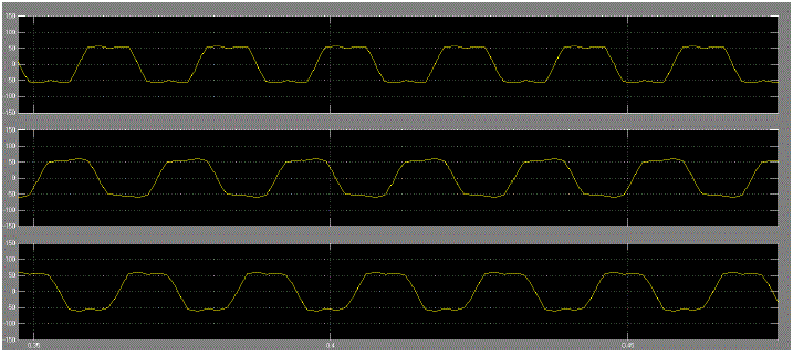
| i) Back EMF’s : The BLDC motor has trapezoidal waveform | ||||||||||||||
 |
||||||||||||||
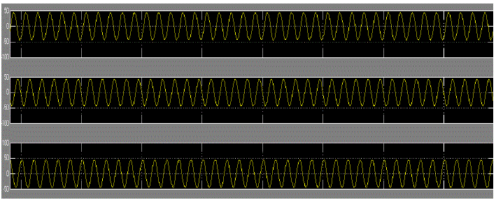
| ii) Stator currents | ||||||||||||||
 |
||||||||||||||
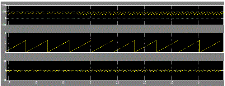
| iii) Speed, Rotor Position, Elctromagnetic Torque | ||||||||||||||
 |
||||||||||||||
CONCLUSION |
||||||||||||||
| In this paper simulation of five level cascaded mli is done using MATLAB. The three phase voltages are fed to MATLAB model of Bldc motor.The simulation results shows the performance characteristics of Bldc motor, i.e. induced back emf is of trapezoidal in shape. The stator currents and electromagnetic torque magnitudes are also obtained in the graphs. The rotor position found out at every instant and is as shown in the graph. | ||||||||||||||
Tables at a glance |
||||||||||||||
|
||||||||||||||
Figures at a glance |
||||||||||||||
|
||||||||||||||
References |
||||||||||||||
|