ISSN ONLINE(2319-8753)PRINT(2347-6710)
ISSN ONLINE(2319-8753)PRINT(2347-6710)
|
Visit for more related articles at International Journal of Innovative Research in Science, Engineering and Technology
In a Pressurized Heavy Water Reactors (PHWR) Channel Outlet Temperature is a function of Channel Power and Channel Flow. Channel Flow can be varied for different Inlet and Outlet header pressures. Calculation of Channel Out let Temperature at various Flow distribution for the constant Channel Inlet temperature and Power Level is necessary for the prediction of different states of the core behaviour at various Loss of Coolant due to the various header and feeder line leakage or rupture. Channel out let temperature is an absolute safety featured parameter in nuclear reactors. Temperature monitoring for individual channels for different channel flow is a challenging task and Individual channel outlet temperature is necessary for calculating the coasting down pattern of the flow during slow reduction of gross flow after loss of power to the circulating pumps. This Temperature difference (Outlet temperature- Inlet temperature) is proportional to the thermal power produced by each channel. Since measurement of out let temperature using instruments in all the channels is not feasible due to its complexity and economic considerations. An algorithmic approach is modelled for calculating the Channel Outlet Temperatures simulating the flow at various header pressure conditions which will change at various operating as well as at different shut down (S/D) conditions. The design Channel Outlet temperatures are matched with the calculated Channel Outlet temperatures for the design flows and considering the various losses due to the flow barriers at normal operating conditions. The Channel outlet temperature is simulated at different operating and at various core flow states by the channel flow which is in turn changed by changing the inlet (I/L) header and outlet (O/L) header pressures. An algorithm is presented to compute the Channel Outlet Temperature at various Channel Flows.
Keywords |
| Pressurised Heavy Water Reactors, Channel Outlet Temperature algorithm, Core flow conditions,. |
INTRODUCTION |
| Coolant in a nuclear power plant plays an important role to transport the primary heat from the core to secondary system to have the effective power generation. By monitoring Channel outlet temperature, The system directly detects the inadequate coolant flow /abnormal fuel condition in any channel. If the temperature rise of the coolant channel is not excessive considerable variation in the coolant flow can be tolerated without the fuel or structure being overstressed to dangerous extent. As a consequence, CTM system has eliminated the necessity of flow monitoring in 97% of the fuel channels thus greatly reducing the number of flow elements, tubes, instruments, welded joints and mechanical joints which carry heavy water of high pressure and temperature. Only about 3% of the fuel channels i.e 8 out of 306 channels are flow monitored these 8 channels are fully instrumented by adding well type RTDs at inlet and outlet to monitor differential temperatures across the channels. these channels are selected to be representative of 8 zones (1 per zone ).Abnormal rise in PHT Temperature reflects the presence of abnormal situation in reactor operation. which can be either due to low coolant flow or high reactivity changes. If such abnormal situation is allowed to exist without plant trip or any corrective action like setback , it may lead to unsafe conditions like damaging fuel or its cladding. Reactor trip is initiated by ‘high N’ trip in case of high reactivity changes and by high PHT pressure trip. in the case of sudden flow reduction to 30% normal flow. Under this situation CTM system provides backup protection only. But excessive rise in PHT temperature of a particular channel cannot be detected by either “High PHT Pressure “or “High N”. Only CTM system can detect such abnormality and provide set back action when temperature exceeds 299 deg C with 1 Deg margin, so that the PHT temperature is not allowed to rise beyond its boiling point i.e.300 deg C at PHT pressure of 87Kg/Cm2. On safety considerations the boiling point is 300 Deg.C is so chosen to obtain maximum margin between actual temperature of fuel/cladding and their respective melting points. This also avoids steam formation. As PHWR is having positive void coefficient of reactivity, excessive boiling of PHT is to be avoided. Therefore, an algorithmic approach is modelled for simulating the flow at various header pressure conditions which will change at various operating as well as at different S/D conditions.[1] |
GENERAL DESCRIPTION |
| The PHWR is a pressure tube type reactor with heavy water as moderator and coolant, and natural uranium Dioxide UO2 as fuel. Pressure tubes, Numbering in the entire 306 channels Zr-2.5% Nb are arranged horizontally in a square lattice of pith22.86cminside a large cylindrical vessel referred to as calandria vessel. These pressure tubes, also called the coolant channels contain the fuel and heavy water coolant at very high temperature and high pressure. The fuel, in the form of small fuel bundles of 49.53 cm length, is stacked along the length of the pressure tube. There are 10 such bundles in the operative portions of the core., with one bundle each on either side outside the core. The fuel bundles consist of 19 rod clusters. Each rod has a zircalloy tube as canning containing a number of short UO2 fuel pallets with a small gap filled with Argon and Helium Mixture. There are number of small studs (Split Spacers) welded on to the canning tube to allow proper separation and coolant flow |
| Each pressure tube having hot coolant D2O flow, is thermally isolated from the clod heavy water D2O moderator present in the calandria vessel, by a concentric calandria tube. The pressure tubes are centered and partially supported in the calandria tubes by garter springs spacers. Dry Carbon dioxide is circulated in the annular space between calandria tube and pressure tube, whose moisture content is monitored for integrity check on calandria tubes and pressure tubes.[2] |
PHT SYSTEM |
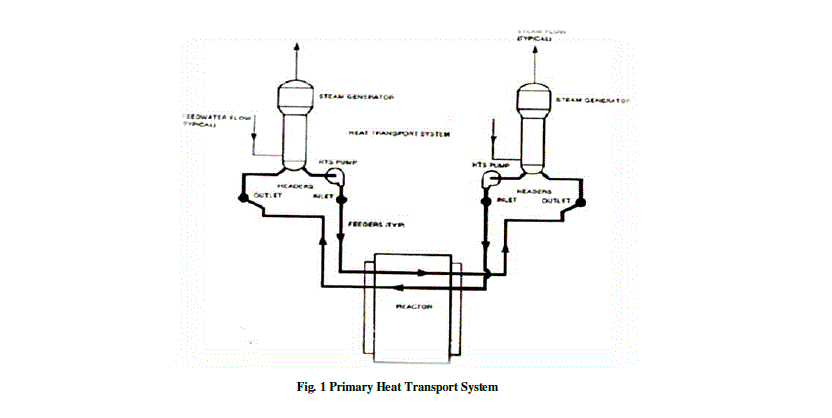
| The Primary Heat Transport (PHT) System main circuit provides the means for transferring the heat produced in the fuel to the feed water in steam generator (SG) in which the steam is generated to run the turbine. The heat transport medium is pressurised heavy water and is circulated through the main circuit by primary circulating pumps (PCPs). Bi-directional fuelling adopted for uniform neutron flux necessitates opposite bi-directional flow in adjacent channels. This has been accomplished by a series-parallel arrangement which has lower hold-up, lower piping cost and lower hydraulic losses as compared to parallel arrangement. [3] |
 |
| The principal features which the system incorporates are given below : |
| a) Continuous circulation of coolant through the reactor at all times by various modes as listed below : |
| i) Normal operation By primary circulating pump. |
| ii) Sudden loss of power By inertia of pump flywheels to pumps and rotating assemblies to avoid a sudden drop in coolant flow for a period of about 120 seconds. |
| iii) Thermo siphoning By placing the steam generator and inlet and outlet header above the elevation of reactor core. |
| iv) Shutdown cooling By operating shutdown cooling pumps through heat exchangers below 1500C. |
| v) Loss of primary coolant (LOCA):By injecting heavy water from heavy water accumulator when the pressure falls below 55 Kg/cm2 and there after if the pressure continues to fall by light water injection at 32 Kg/cm2 along with light water injection conditional signals. Subsequently the core is cooled by pumping water from the suppression pool by emergency core cooling pumps through heat exchangers. |
| vi)Small leakages: Keeping the system pressurised with heavy water and recirculation of leaked heavy water back into the system. through small leak handling system. |
| b) Pattern of coolant flow rates through coolant tubes is compatible with pattern of heat production in individual coolant tubes to yield a common increase in coolant temperatures in all channels across the reactor. |
| c) Controlled pressure at the reactor outlet headers. |
| d) Over pressure relief. |
| e) Addition of coolant to and removal of coolant from the system. |
| f) Control of dissolved gases in coolant. |
| g) Purification and pH control of coolant. |
| h) Provision for supply of high pressure heavy water to the fuelling machines. |
| i) Accessibility of all components during shut down and accessibility of some during operation. |
| j) Heavy water leakage collection from potential leaky points in the system. |
| k) Provision for draining steam generators in case of any maintenance work and header level control. |
PRIMARY HEAT TRANSPORT SYSTEM PRESSURE CONTROL |
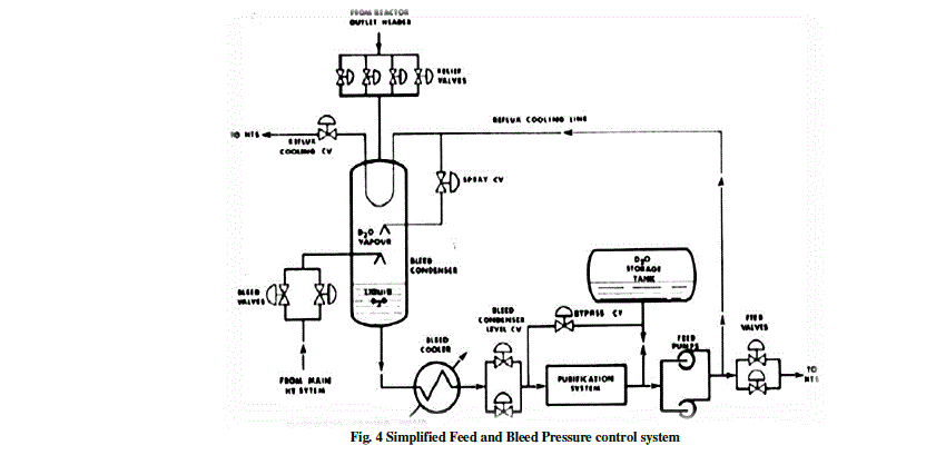
| PHT system pressure has to be controlled within specified limits. If we go outside these limits, we jeopardise reactor safety. For example, low pressure impairs fuel cooling and may result in severe PHT system pump cavitations or even vapour locking. Two different methods of PHT system pressure control are used in our stations. One is based solely on a feed and bleed system whilst the other uses a pressurizer in addition to a feed and bleed system. At PNGS, there are no designated boiling channels. Hence, the PHT system is designated solid because no compressible vapours are present. A change in volume occurs due to the volumetric expansion or contraction of the reactor coolant, which is a function of temperature. The control scheme is designed to keep the average PHT coolant temperature constant during load changes. As such, under normal operating conditions the feed and bleed system effectively controls PHT coolant pressure. Now let’s take a look and see how it does so. The feed-and-bleed system can be seen in Figure 4-1. Coolant is bleed from the system via bleed valves connected to the PHT system pump suction headers. In order to maintain pressure, pressurizing pumps return the feed to the PHT system. |
 |
DESIGN OBJECTIVES |
| Channel Temperature monitoring system monitors |
| i) The temperatures of the Coolant (PHT)at the outlet of all the 306 channels. |
| ii)The differential temperature of 8 selected channels. This system mainly |
| a) detects low coolant flow /excessive rise in temperature and apply corrective action i.e. generating setback signals for reactor safe condition. |
| b) Provides signal for flux tilt control and |
| c) Helps in efficient fuel management by monitoring channel outlet temperatures and other related temperatures. |
| By monitoring Channel outlet temperature, the system directly detects the inadequate coolant flow /abnormal fuel condition in any channel. If the temperature rise of the coolant channel is not excessive considerable variation in the coolant flow can be tolerated without the fuel or structure being overstressed to dangerous extent. As a consequence, CTM system has eliminated the necessity of flow monitoring in 97% of the fuel channels thus greatly reducing the number of flow elements, tubes, instruments, welded joints and mechanical joints which carry heavy water of high pressure and temperature. Only about 3% of the fuel channels i.e 8 out of 306 channels are flow monitored these 8 channels are fully instrumented by adding well type RTDs at inlet and outlet to monitor differential temperatures across the channels. These channels are selected to be representative of 8 zones (1 per zone ).Abnormal rise in PHT Temperature reflects the presence of abnormal situation in reactor operation. which can be either due to low coolant flow or high reactivity changes. If such abnormal situation is allowed to exist without plant trip or any corrective action like setback , it may lead to unsafe conditions like damaging fuel or its cladding. Reactor trip is initiated by ‘high N’ trip in case of high reactivity changes and by high PHT pressure trip. In the case of sudden flow reduction to 30% normal flow. Under this situation CTM system provides backup protection only. But excessive rise in PHT temperature of a particular channel cannot be detected by either “High PHT Pressure “or “High N”. Only CTM system can detect such abnormality and provide set back action when temperature exceeds 299 deg C with 1 Deg margin, so that the PHT temperature is not allowed to rise beyond its boiling point i.e.300 deg C at PHT pressure of 87Kg/Cm2. On safety considerations the boiling point is 300 Deg.C is so chosen to obtain maximum margin between actual temperature of fuel/cladding and their respective melting points. This also avoids steam formation.[1] |
| As PHWR is having positive void coefficient of reactivity, excessive boiling of PHT is to be avoided. Power Output of the reactor is proportional to average neutron flux in the core which can be increased either by increasing peak flux in the centre or by changing the flux shape so that a greater portion of the core sees high flux. Former is limited by maximum allowed temperature of the fuel and hence later is carried out by proper positioning of adjuster rods through flux tilt control with a signal from CTM system. The selected channels are fully instrumented to measure the coolant flow, I/L temperature and outlet temperature accurately. The flow and temp. Signals of these selected channels are fed to COIS (Computerised Operator Information System)for monitoring flow inlet temperature and computed parameters like diff. temperature and channel power of the selected channels. These datas are useful for analysing the reactor status under normal or abnormal condition.(eg during big LOCA condition, the outlet temperature falls below the the Inlet temperature.i.e. Differential temperature becomes negative and coolant flow is reversed.) Also it facilitates the comparison of the surface RTDs and the thermo well RTDs readings used for selected channel temperature measurements and estimate the static in-situ error of surface RTDs and the thermo well RTDs readings used for selected channel temperature measurements and estimate the static in situ-error of surface RTDs.[2] |
PURPOSE OF THE SYSTEM |
| Low flow will result in temperature rise in the fuel channel which may lead to fuel failure if the channel is left unmonitored [2]. The detection of low flow can be achieved by one of the two methods. |
| (1) Directly by measurement of channel flow. |
| (2) Indirectly by measurement of channel outlet temperature or indirectly by varying pressure difference in the system. While deciding the type of measurement, emphasis was given to have minimum number of welded joints, less number of tubes, instruments, mechanical joints, instruments to tube joints etc. so that chances of leakages are reduced as the system carries heavy water at high pressure and high temperature with the radioactivity present in the fluid. |
DESIGN BASIS |
| The number of channels and their locations which employ channel flow measurement are decided on the following consideration [2]. |
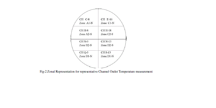
| (1) The channel thus selected should represent entire zone i.e. at least one channel shall be selected from each zone. |
| (2) Equal number of channels is selected from north and South zone. This is as shown in Fig. 2 below. |
 |
 |
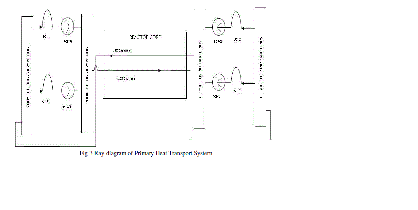 |
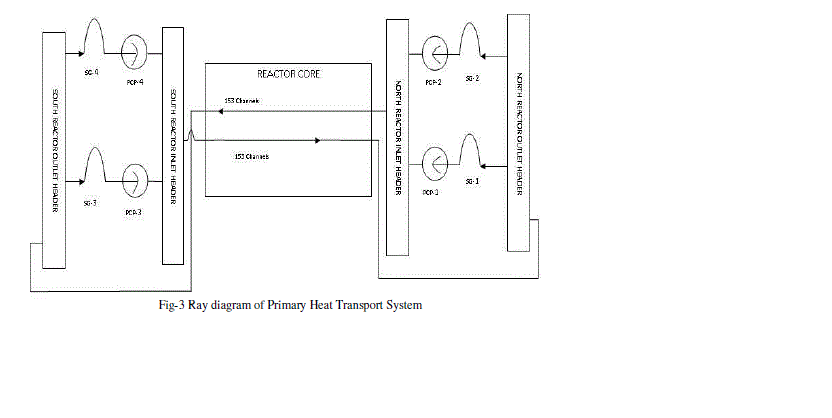
| Fig-3shows the coolant flow path in Primary Heat Transport System. The thermal rating of the 306 fuel channels varies according to the flux pattern with a maximum to minimum ratio of approximately 2.4.It is necessary to match the coolant flow to the heat generated in each channel to minimize the variation in outlet coolant temperature. Uniformity in coolant conditions is essential as these are basic parameters in the channel structural design and in the plant thermal cycle. The flow resistance of feeders is designed to provide an appropriate flow of coolant to each channel at rated difference in circulating head between the reactor headers. The hydraulic analysis takes account of the channel flow losses which include an orifice element mounted on the end fitting shield plug and also a inconel restrictions orifice in some of the inlet feeders [4]. |
| The headers are connected to two SG-Pump Units on each side of the reactor. The feeders and header system is symmetrically arranged with half of the fuel channels supplied with the coolant from each end of the reactor. The direction of the coolant flow is opposite to adjacent channels, and thus the feeders at each face connected alternately to the I/L and O/L headers.[5,6]These channels are classified into 153 North Upstream channels fed from NRIH to SROH and 153 South Upstream channels fed from SRIH to NROH. The overall flow control is done as per the design flow pattern through the feeder and the total PCP flow is matched with total out coming flow through the reactor. This balances the actual flow with channel flow [5]. |
ALGORITHM FOR CALCULATING THE FLOW THROUGH EACH COOLANT CHANNEL BASED ON HEADER PRESSURE DIFFERENCE. |
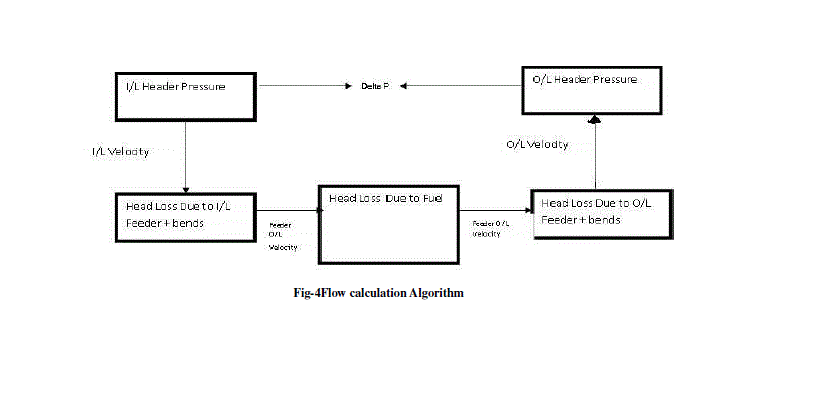 |
| Δ P = Ip - Op Kg/sq.cm |
| (Δ P/σ) = TL=V1 2*0.89 |
| V1 2=TL/0.89 |
| V1= √ (TL/0.89) = (Δ P/σ) |
| Actual Flow is calculated using the formula: QActual=V1*A1*3600*885.4 |
| The actual flow calculated is compared with design flow as shown in Fig-4 and the result found is within 5% tolerance. [5,6] |
CONCLUSION |
| It has been found from analysis that the calculated Channel Outlet Temperature matches with the design Temperature through the individual channel within the tolerance of ±5%.The Channel Outlet Temperature is calculated for different Channel flow which is a function of header pressures. The result is compared with the calculated in the instrumented channels and the Temperature calculated in the commissioning procedures at various Core Flow conditions. The calculated COT matches with the Design COT within the tolerance of ±5%. |
ACKNOWLEDGEMENTS |
| This work is done in coordination with the Nuclear Power Corporation India Limited, Kaiga Generating Station Staff and Management. Authors are Thankful Mr.B.Vinodkumar (Operation Superintendent Kaiga Generating station)Mr.H.N.Bhat (Site Director Kaiga Generating Station) to have the project realistic and working successfully and to meet our expectation. We highly appreciate the efforts of the management to use this as a tool for safe operation. We are also thankful for all the readers and highly appreciate suggestions for enhancing the performance of the system. |
References |
|