ISSN ONLINE(2319-8753)PRINT(2347-6710)
ISSN ONLINE(2319-8753)PRINT(2347-6710)
Osama Omer Adam Mohammed1, Dr. Awadalla Taifor Ali 2
|
| Related article at Pubmed, Scholar Google |
Visit for more related articles at International Journal of Innovative Research in Science, Engineering and Technology
this paper presents two efficient methods for speed control of a separately excited D.C motor using PID control and fuzzy logic control. The motor was modelled and converted to a subsystem in SIMULINK. The simulation development of the PID controller with the mathematical model of DC motor is done using Ziegler- Nichols method and trial and error method. The PID parameter is tested with MATLAB/SIMULINK program. (FLC) the fuzzy logic controller is designed according to fuzzy rules so that the systems are fundamentally robust. There are 25 fuzzy rules. The FLC has two inputs. One is the motor speed error between the reference and actual speed and the second is change in speed error (speed error derivative).For comparison purpose, PID and Fuzzy controllers have been tested using MATLAB/SIMULINK program for speed under load and no load conditions. The result shows that the Fuzzy controller is the best controller than PID controller. In addition fuzzy logic controller Demonstrates good performance, faster design and work well for high-order and nonlinear and shows the efficiency over the PID controller.
Keywords |
| DC motor, speed control, Proportional- Integral Derivative controller PID, and Fuzzy logic controller. |
INTRODUCTION |
| Direct current (DC) motor is a current (DC) motor is a fairly simple electric motor that uses electricity and magnetic field to produce torque. DC motors consist of one set of coils, called armature winding, inside another set of coils or a set of permanent magnets, called the stator. Applying a voltage to the coils produces a torque in the armature, resulting in motion. DC motor has been widely used in industrial applications due to its simple structure, low initial cost, high accuracy control system, high control performance, high reliability and provide excellent control of speed for acceleration and deceleration. There are several applications required a high start-up torque. The D.C. motor, by its very nature, has a high torque versus. Falling speed characteristic and this enables it to deal with high starting torques. DC motors is very important in industrial as well as other purpose applications such as still rolling mills, electric trains, electric vehicles, electric cranes and robotic manipulators require speed controllers to perform their tasks. There are several method used to control in DC motor such as Proportional Integral Derivative (PID) controller, fuzzy logic controller (FLC) and Neural Network controller. |
MODEL OF DC MOTOR |
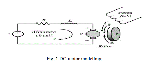
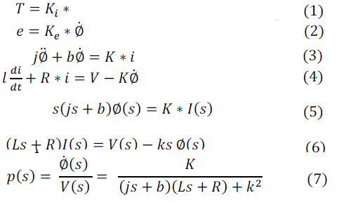
| A common actuator in control system is the DC motor it directly Provides rotary motion and, coupled with wheels or drums and cables, can provide transitional motion. [1] The electric circuit of the armature and the free body diagram of the rotor are shown in the Figure (1): |
 |
 |
DESIGN SIMULATION MODEL FOR DC MOTOR |
| `In this paper used a classical model for DC motor with constant excitation, and SIMULINK model it was generated of Figure. 2 |
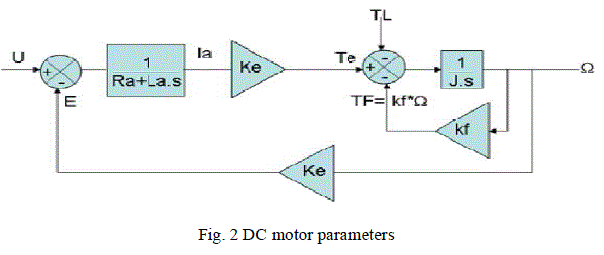 |
| Matlab-simulink program is used, to drawing the above model diagram, and selected all component of input and output system, created subsystem and named the subsystem as DC motor. |
| PID CONTROLLER DESIGN |
| Fig. 3 shows the SIMULINK block diagram of speed control of dc motor using PID controller. Step input is given to the controller. The error signal is given to the PID controller. [3] Subsystem signifies the motor model as shown in Fig.3 |
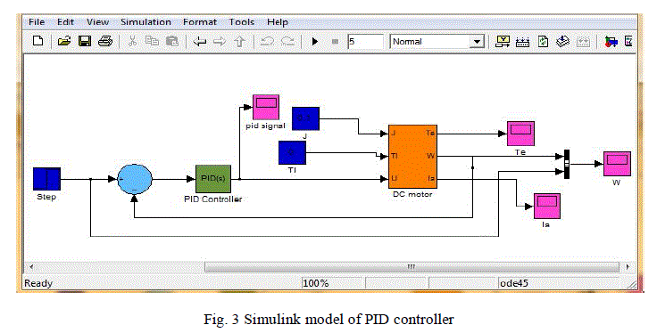 |
| The aim of the controller is to obtain the Fast responses and Good stability for the control system.PID controller is design for separately excited DC Motor using MATLAB. The system as shown in Figure (3) is tuned for the following parameters for the PID controller to get desired speed: KP = 2, KI = 14, KD = 0.05 Major problems in applying a conventional control algorithm in a speed controller are the effects of nonlinearity in a dc motor. The nonlinear characteristics of a dc motor such as saturation and friction could degrade the performance of conventional controller. Therefore there is need of a controller which can overcome disadvantages of PID controller |
| FUZZY LOGIC CONTROLLER |
| Fuzzy control systems are knowledge-based or rule-based systems. The heart of a fuzzy system is a knowledge base consisting of the so-called fuzzy IF-THEN rules. A fuzzy IF-THEN rule is an IF-THEN statement in which some words are characterized by continuous membership functions. [4] |
| The objective is to implement FLC for controlling the speed of a dc motor. The change of speed of error plays important role to define controller input. Consequently FLC uses error (e) and change in error (ce) for linguistic variables which are generated from control rules. The output variable is the change in control variable of the motor drive. To overcome the problem of PID parameter variation, a normalized fuzzy controller with adjustable scale factor is suggested. In this paper the fuzzy controller is built according to accumulative knowledge of the previous tuning methods. The fuzzy controller designed has the following parameters. |
| 1. membership function of the input/output signal have the same universe of discourse equal to 1 |
| 2. the number of membership function for each variable is 5 triangle membership functions denoted as NL (negative long), NS (negative small), ZE (Zero error), PL (positive long) and PS (positive small) |
| 3. fuzzy interference system is Mamdani method |
| 4. fuzzy interference method are ”min” for AND, ”max” for OR, ”min” for implication, ”max” for aggregation, and ”centroid” for Defuzzification. |
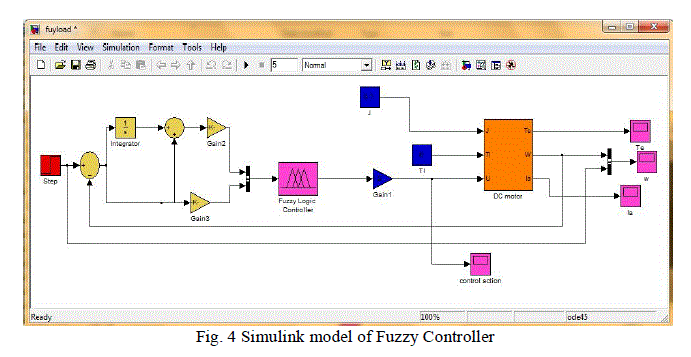 |
| The simulink model of fuzzy logic controller of DC motor is shown in Fig.4. The simulink model is evaluated for the response of speed, error and change of error, used trial and error method for tuning FLC parameters. [5] |
SIMULINK IMPLEMENTATION AND EXPERIMENTAL RESULTS |
| Simulation Results for System under no Load. |
| In this section the motor is considered without load, but in real life this never happens because there is always friction in the motor system acting as a load and requiring the motor to output torque to overcome it. Here simulink program is used to test the system with different controllers and observing the performance of velocity and control actions waveforms. |
| simulation result for system without controller |
| In this section the DC motor tested without any controllers as open loop voltage control. |
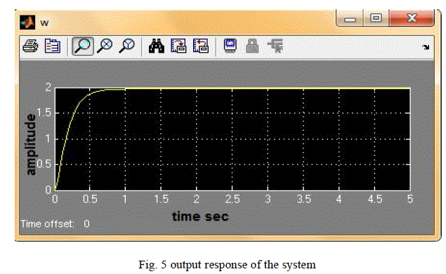 |
| Fig. 5 its illustrates the response for the system with unit step input, the maximum speed of 2 rad/sec, the motor takes 1 second to reach its steady-state speed with overshoot 90%. |
| Simulation result using PID controller: |
| From figure 3, by substituting the parameter values of simulink model after tunning KP = 2, KI = 14, KD = 0.05, and unit step response, the following response is appeared. |
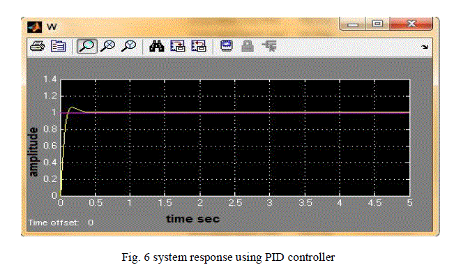 |
| The Fig. 6 illustrates the response of the system with unit step input. And the motor achieve the desired speed in 0.55 second, the motor with PID has overshoot initially 0.6% which undesired, if the input voltage is fixed to certain level that mean the controller requirement of voltage more than the certain level then this is not a good in results |
| Simulation result using fuzzy controller: |
| From fig 4 the trial and error method is used for tuning FLC parameters, The values of FLC parameters are gain1= 1.01 , gain2= 11 and gain3 = 1, Figure (7) illustrate the response of system with a unit response. |
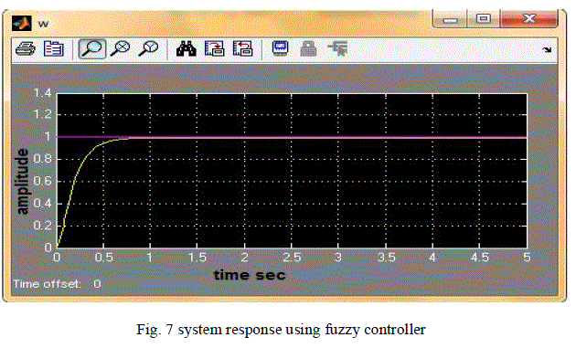 |
| Fig.7 illustrates the system response of FLC controller. The output speed plot is a smooth and no overshoot in the initial, at t=0 so that this controller is more preferable to use for the system. |
| Simulation Results for System under Load |
| In this section the motor is considered with load which is applied at t=5. The torque load is increased from zero to =0.1 Nm/A. |
| System Simulation results without controller and under load. |
| In this section the DC motor is connected with load torque to (tl) =0.1 Nm/A, without controller to note the behaviour of system |
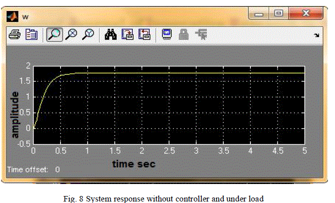 |
| Fig. 8 shows that when torque load TL is applied to motor the speed is decreased. And this decrease of speed is not good for the performance of motor because if this motor is set in real application (engine) then the torque load decreased or increased often and this reduced speed is effect in performance and not provide the desired results. So in order to overcome this problem used PID and fuzzy controller in next sections |
| ïÃâ÷ System Simulation result using PID controller |
| From fig 3 the system is modelled to provide load torque to DC motor, the dynamic response of the system is captured using scope with step response at t=0.5 for torque load (Tl) =0.1 Nm/A. |
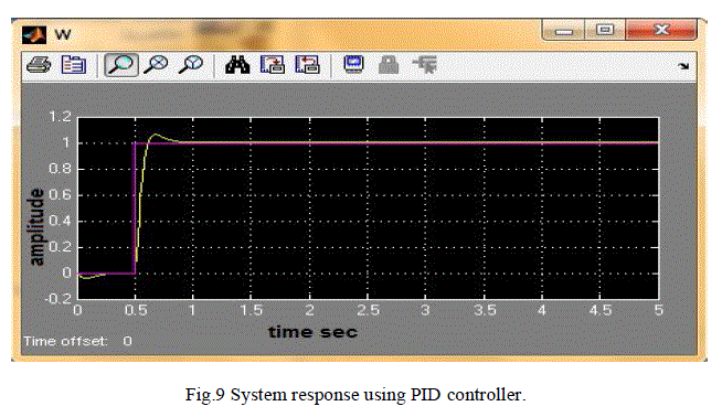 |
| Fig.9 show when torque load (Tl) =0.1 Nm/A, is applied at t=5 second and unit step response t=0.5, the speed reduced but speed again got its reference point, so PID controller solve the problem of DC motor when torque load changed and the speed remain constant at the reference point. |
| ïÃâ÷ System simulation result using fuzzy controller |
| From fig 4 the simulink model is evaluated for the response of speed error and change of error, when torque load (Tl) =0.1 Nm/A were applied to DC motor at 5 second, the response of speed were represented in fig 10. |
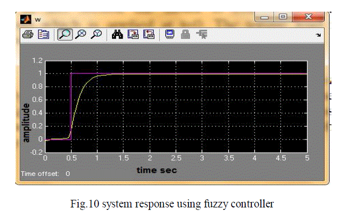 |
| Fig. 10 show when torque load is applied (Tl) =0.1 Nm/A, /A at t=5 second with a unit step response at t=0.5 the speed is not effect and it remain constant, this is advantage of fuzzy controller so it can say the fuzzy controller is the better than PID controller. |
CONCLUSION |
| In this study the DC motor is mathematically modelled and then simulated using MATLAB program version 2010. PID controller is a simple controller, it provides easy, cheap solution in industries, and the tuning is very easy in addition PID its work only in SISO systems, while fuzzy controller works on both SISO and MIMO systems and it provides better result than conventional controller. PID controller needs more suggestion for chosen the “ïÿýïÿýïÿýïÿýïÿýïÿý” to calculate PID parameters, and Fuzzy controller uses trial and error method to calculated Fuzzy parameters. The PID control needs constantly adjustment in order to achieve better control performance. Fuzzy self-tuning parameters controller is automatically adjusted parameters according to the speed error and the rate of speed error-change, and the fuzzy logic response is compared with that of conventional PID controller. The results show that the overshoot, settling time and control performance has been improved greatly by using Fuzzy Logic controller. When applied torque load 0.1 N-m at time t = 5 sec. the speed reduced but speed again got its reference point when used PID controller but in fuzzy controller the speed is not affected and it remain constant, this is advantage of fuzzy controller so it can say the fuzzy controller is the better than PID controller. |
References |
|