ISSN ONLINE(2319-8753)PRINT(2347-6710)
ISSN ONLINE(2319-8753)PRINT(2347-6710)
Sangram Keshari Samal1, Dr. Dilip A Shah2, Bharath M3, Abhinash Sahoo4
|
| Related article at Pubmed, Scholar Google |
Visit for more related articles at International Journal of Innovative Research in Science, Engineering and Technology
The near-field flow structure of a wing tip vortex behind a sweptback and tapered NACA 0015 wing was investigated using Computational Fluid Dynamics (CFD) code at Re of 1.81 x 10⁵. In this paper, Numerical simulations of the tip vortices was carried out at a geometric angle of attack 8° and the numerical results of tangential velocity of tip vortex is compared with the experimental result done by P. Gerontakos and T. Lee at McGill University low speed wind tunnel at the velocity equal to 35 m/s. The numerical result that was obtained by using CFD code shows a good agreement with the experimental result. The coordinates of the vortex-core location are closely captured along the downstream of flow and the variation of the vortex flow quantities with different angle of attack are investigated. Also circulation at three different downstream location of the trailing edge are calculated
Keywords |
| Tip-vortex, CFD, Circulation, Downwash |
Nomenclature: |
| uc Core axial velocity |
| U∞ Free stream velocity |
| vθ Tangential velocity |
| x Stream wise direction |
| y Normal to wing direction |
| z Span wise direction |
| àøÃ⬠Vorticity |
| Γ Circulation or vortex strength |
| Re Reynolds number |
| λ Taper ratio (ct/cr) |
| cr Root chord |
| ct Tip chord |
| r Radius of vortex |
| AR Aspect Ratio |
I. INTRODUCTION |
| Wing tip-vortex flow around lifting surfaces such as wings and propeller blades has long been a topic of both fundamental and practical interest in the aerospace industry for its impact on various aspects of aerodynamic performance. The investigation of trailing vortices is an important task in aerodynamics because of their influence on following aircraft and because of the energy contained in these vortices, which is directly related to induced drag. Achieving this desired accuracy is a demanding task, since high grid resolution is necessary at the wing’s boundary and in the vortex region, where velocity gradients are high. Consequently, this leads to high numbers of cells and to very long stretched cells at the wall boundaries. |
| In a finite wing, there is an opportunity for the pressures acting on the upper and lower surfaces to interact near the wing tip[1]. The shorter the distance between the wing tip, the larger the downwash velocity and the induced drag[2]. The trailing vortex system also generates an upwash in the regions beyond the wing span and a downwash inside the wing span. This downwash produced by the trailing vortex system adds to the downwash produced by the bound vortex system[3]. |
| Aerodynamic efficiency can be improved by increasing the maximum lift-to-drag ratio at the cruise flight condition. Because induced drag is typically 30 percent or more of the total drag on a subsonic transport in cruising flight[4]. A 10% drag reduction on a large military transport aircraft is estimated to save up to 13 million gallons of fuel over its lifetime[5]. The world total jet fleet is estimated to be around 17 thousand aircraft[6]. Such reduction in drag could result in fuel savings in fuel up to 1x10¹⁰ U.S. dollars ($). This drag is even more significant at low speed, during take off conditions, where it can account for 80-90% of the aircraft drag[7]. |
| Besides the advantage of lowering operating costs, reducing wingtip shed vorticity, and therefore induced drag, may also reduce global warming because of the lower fuel consumption. The world’s commercial jet aircraft generate more than 600 million tons of carbon dioxide per year[8]. The techniques for its tip vortices reduction include winglets, wingtip sails, Raked wing tips and Ogee tips. Much of the development work for the winglet was initiated by Whitcomb at NASA[9],[10]. |
| This paper presents the validation of CFD code against McGill University experiments data and then to find the variation of the circulation at different areas to the right of the wingtip vortex core and tangential velocity at one chord downstream of the trailing edge is obtained. Also shows the reduction of wing tip vortex by applying suction on the wing tip. |
II. PROCEDURE |
| A. Overview |
| This paper presents a comparison between wingtip vortex flow field done by CFD simulations and experimental measurements done at McGill University by P. Gerontakos and T. Lee,[11] as a validation of the present numerical CFD simulations and several different parameters are computed and presented in graphical format. |
| The present simulations were run in ANSYS 13.0, which models fluid flow and heat transfer problems in complex geometries. This commercial CFD software solves the general transport equations using the finite volume method. Steady-state, transient, incompressible, compressible, inviscid, viscid, laminar, and turbulent flows can be solved with Fluent. |
| B. Complete Geometry Case |
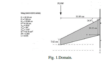
| The computational domain includes a half-wing inside a wind tunnel (Fig. 1) such as the one used by P. Gerontakos and T. Lee [11]. The model is an untwisted sweptback, tapered wing with an aspect ratio of 3.654, a taper ratio of 0.375, a semi-span of 51 cm, and a wing area of 713 cm 2 . The root chord was 20.3 cm and the tip chord was 7.6 cm. The square tipped wing had a NACA 0015 section throughout at 8° angle of attack. Free stream velocity was 35 m/s. The locations of the downstream vortex-flow measurement planes (denoted by the dashed lines) are shown in Fig.1. The sweep angle at 0.25-chord location was set at 240. The root chord cr was 20.3 cm and the tip chord ct was 7.6 cm. The square tipped wing had a NACA 0015 section throughout. |
 |
| C. Mesh generation |
| The geometry was imported to ANSYS ICEM CFD to generate meshes. ANSYS ICEM CFD provides advanced geometry acquisition, mesh generation, mesh optimization, and post-processing tools to meet the requirement for integrated mesh generation and post processing tools for today’s sophisticated analyses. Maintaining a close relationship with the geometry during mesh generation and post-processing, ANSYS ICEM CFD is used especially in engineering applications such as computational fluid dynamics and structural analysis. |
| D. Solver configuration |
| After generating mesh it was feed to a solver to calculate the flow properties. Here the solver used was a FLUENT. ANSYS FLUENT is a state-of-the-art computer program for modelling fluid flow, heat transfer, and chemical reactions in complex geometries. ANSYS FLUENT uses a client/server architecture, which allows it to run as separate simultaneous processes on client desktop workstations and powerful computer servers. This architecture allows for efficient execution, interactive control, and complete flexibility between different types of machines or operating systems. ANSYS FLUENT provides complete mesh flexibility, including the ability to solve the flow problems using unstructured meshes that can be generated about complex geometries with relative ease. Supported mesh types include 2D triangular/quadrilateral, 3D tetrahedral/ hexahedral/pyramid/wedge/polyhedral, and mixed (hybrid) meshes. ANSYS FLUENT also allows to refine or coarsen the mesh based on the flow solution. |
| E. Boundary Conditions |
| The inlet boundary condition was defined as a uniform inlet velocity = 35 m/s. The outlet boundary condition was based on a pressure outlet condition. The wind tunnel walls were defined as slip walls with a uniform velocity of V∞, except on the wall of symmetry, where the normal velocity component were set equal to zero. The wing surface was defined as a stationary surface. |
| F. Circulation across the Wingtip Vortex |
| The circulation, denoted by Γ is defined as [12]. |
| Minus sign appears in above equation to account for positive-counter clockwise sense of the integral and positivecounter clockwise sense of the circulation |
| For a plane it becomes [13] |
 |
 |
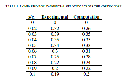
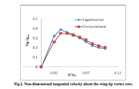
| Table 1 and Fig. 2 show a comparison between tangential velocity (vθ) to the free stream velocity (U ) measurements done by P. Gerontakos and T. Lee and simulations done in Fluent. The simulations show good agreement with the experimental data. |
 |
 |
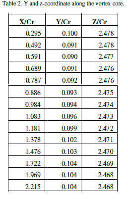
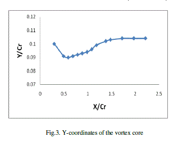
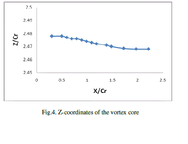
| The location of the vortex-core (y-coordinate, and z-coordinate) along the vortex core are closely captured and represent in Table-2 and Fig. 3, 4, respectively. |
 |
 |
 |
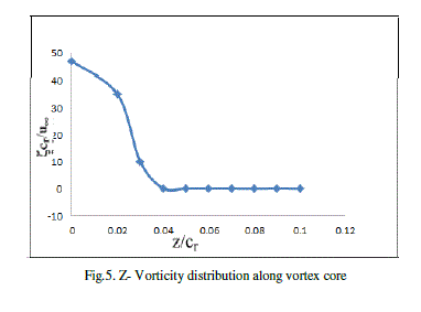
| Vorticity is calculated for x/cr=0.625 at angle of attack 80 and displays the distributions of the no dimensional ïÿý about the vortex centre in Figure 5. |
 |
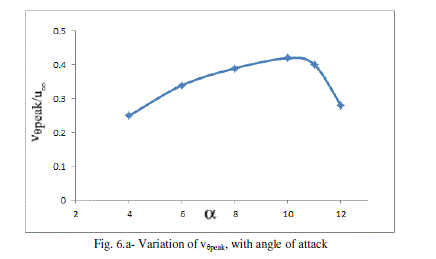
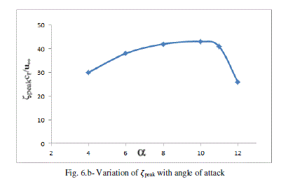
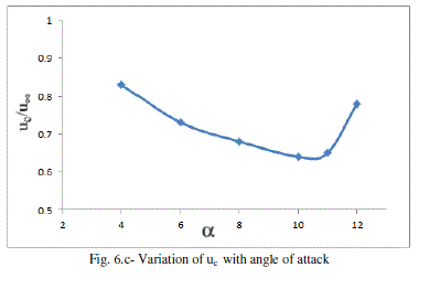
| The variation of the vortex flow quantities (i.e. vθpeak, ïÿýpeak and uc ) with angle of attack are also investigated and is presented in Fig. 6a–c. |
 |
 |
 |
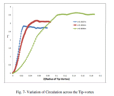
| Circulation is calculated at 3 downstream location (x=0.3567m, 0.4064m and 0.6096m) and displays the distributions across the vortex in Figure 7. The strength of vortex reaches to maximum and remains close to constant for a wide range in each cases. |
 |
IV. CONCLUSIONS |
| The three-dimensional near-field mean flow structure of a tip vortex behind a sweptback and tapered NACA 0015 wing with an AR of 3.654 and a k of 0.375 was investigated at Re =1.81x 10⁵. The CFD simulations done in the current study to reproduce the experimental measurements done by P. Gerontakos and T. Lee,[11] at McGill University has shown very good agreement to predict the formation of wing tip vortices for a sweep back wing. The emphasis was laid upon the level of accuracy with which the tip-vortex can be captured. |
| The non dimensional peak tangential velocity and vorticity were found to increase initial and decrease after angle of attack 100. The location of the vortex-core is closely captured and it is observed the vertical location(Y coordinate) decreases initially and increases after 0.5 x/cr where the vortex-core location along wing span (Z coordinate) deviation is very small. The strength of vortex is calculated at 3 downstream locations. It reaches to maximum and remain close to constant. |
| To summarize, we were able to predict all aspects of the tip-vortex using modern CFD code with commendable accuracy, such as the tangential velocity across the vortex-core, the coordinates of the vortex-core, the strength of the vortex and other vortex flow quantities with a good accuracy |
References |
|