ISSN ONLINE(2319-8753)PRINT(2347-6710)
ISSN ONLINE(2319-8753)PRINT(2347-6710)
S. B. Kandekar1, P. D. Dhake 2, M. R. Wakchaure3
|
| Related article at Pubmed, Scholar Google |
Visit for more related articles at International Journal of Innovative Research in Science, Engineering and Technology
A beam is a one dimensional (normally horizontal) flexural member which provides support to the slab and vertical walls. In a normal beam (simply supported) two zones generally arise, viz. compression zone at top and tension zone at bottom. As concrete is weak in tension, steel is introduced in the tension zone to take the tension, but as strength of concrete is ignored in tension zone with respect to compression zone. So logically no concrete is required in tension side. But this concrete needs to be provided on tension side to act as strain transferring media to steel and may be called as 'sacrificial concrete'. If this concrete has no tension mere than strain transferring, then why to go for same grade of concrete which is used in upper zone? This is basic question which led to the idea of concrete grade reduction in tension zone for RCC beams to reduce construction cost.
Keywords |
| concrete grade reduction, flexural member, sacrificial concrete, strain transferring media |
INTRODUCTION |
| In the ancient time size of walls are large especially in load bearing structures. With the advances in the science and technology Reinforced Concrete Construction (R.C.C) came in to picture. Initially according to Indian standard code of practice IS456-1978, M15 grade of concrete was also permitted to be use in general construction but according to new revision made in IS 456-2000, lowest grade of concrete which can be used in concreting for construction is M20 for mild environment. With the help of creative sense, imagination, understanding and keen observation of structures in nature, scientific knowledge of various aspects of the structures, many dynamic personalities in civil engineering field are coming with new concepts with the help of which there are lots of finding viz. reduction in the thickness of wall, reduction in the beam-column sizes etc. But no research or study has been made until now on replacement of sacrificial concrete in case of deep beams. This is also a research area in structural design. As concrete is weak in tension, to take this tension steel reinforcement is provided at the bottom side of the beam section. As compressive stresses are induced in the zone above the neutral axis, compressive strength of the concrete lying above neutral axis is very important parameter. This induces compressive force in the top zone at a distance of 0.42 XU. (XU –Neutral axis distance from top of section.) The tension force acts at centroid of steel reinforcement provided at bottom of section. The distance between the point of action of compressive force and tension force is called lever arm and it is directly proportional to moment of resistance. Generally being a structural engineer we should concentrate towards the structural as well as functional design of the structure. But while designing, economy of the project is also a major factor. Keeping economy and safety of the structure in mind, we came with the concept of "Partial Beam". |
| A partial beam is a normal beam cast with two grades concrete, one above and other below the neutral axis. Partial beam is a beautiful result of the application of engineering in building construction works to achieve economy as well as reduction in the environmental impact due to construction works. |
II. GENERAL BEAMS |
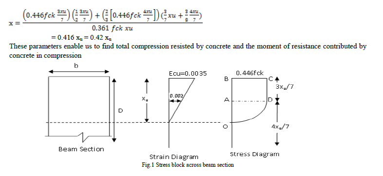
| The idealized stress strain curve for concrete as prescribed by IS code is rectangular parabolic as shown in fig. 1. It consist of a parabola emerging from the neutral axis with its apex lying at the point corresponding to the strain of 0.002 and a rectangular beyond that point terminating at the compression face where the maximum strain is 0.0035. Let xu be the depth of neutral axis below the compression face. The depth of parabolic part of stress block = 4xu/7 Hence depth of rectangular part of stress block = 3xu/7 Area of stress block = Area of rectangle ABCD + Area of Parabola OAD = 0.361 fck xu = 0.36 fck xu The distance of centroid of stress block from compression face is obtained by taking moments of area about the top compression face. |
 |
III. METHODOLOGY |
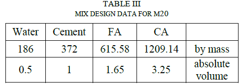
| The experimental program mainly consists of two parts, viz., preparation of the required types of specimens and testing the same. The experimentation is aimed at studying flexural strength of partial beam and studying the crack appearance at the interfaces. The quality as well as the characteristics of the concrete depends on the properties of its ingredients. Hence the preliminary tests were conducted on cement, coarse aggregate and fine aggregate before the commencement of the experimental programme. The designed mix proportions for M30 and M20 grade of concrete are shown in Table I and Table II. |
 |
 |
 |
IV. EXPERIMENTAL PROGRAM |
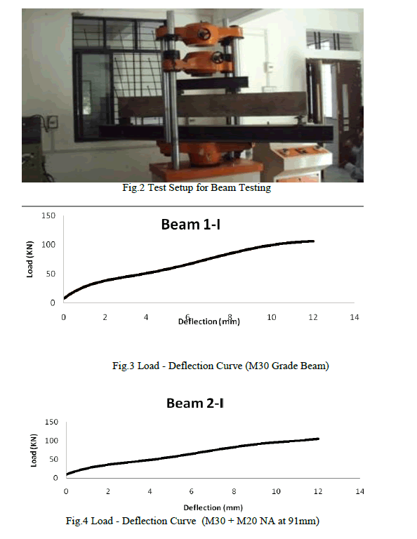
| Separate mix design was prepared for M 30 grade of concrete (1:1.38:2.71). The formwork prepared and ingredients are weighed accurately with weight balance. Ingredients are mixed with the help of concrete mixer. Concrete was placed in the formwork in layers of approximately 15 cm and compacted. Similarly, the layers were successively placed one above the other and compacted. End faces were properly compacted to get smooth finish. After completion of about 10 hours, wet gunny bags were placed on the newly casted beam. For composite beams separate mix design was prepared for M30 grade of concrete (1:1.38:2.71) and M 20 grade of concrete (1:1.65:3.25). Neutral axis is marked with the help of a string stretched between two end plates. Concrete in the tension zone was placed in the formwork in layers of approximately 15 cm and compacted firstly for M20 grade of concrete. Similarly, the layers were successively placed one above the other and compacted. After the level of string was reached, the concreting operation was stopped with M20 grade of concrete. Loading frame was then placed on the Universal Testing Machine. First of all, normal rectangular beam was placed on the loading frame. It is placed exactly at the centre of the loading frame. Simple support with a bearing of about 15 cm is provided beneath the beam as shown in fig.2. Deflection gauge was attached to the beam at the mid span and quarter to the left and right to note down the deflection after the application of the two point load. Load was then applied gradually and uniformly. Simultaneously deflection was noted down carefully. For each deflection corresponding load was observed and noted down. The results are shown in fig.3, fig.4 and fig.5. |
 |
 |
V. DISCUSSIONS |
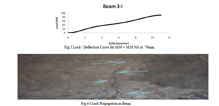
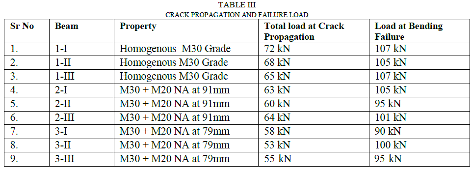
| It is observed that partial beam failed in the same way as the normal beam but the load taken at crack propagation and bending failure are different as shown in fig. 6 and Table III. For M30 grade of concrete beam bending moment at first crack is 32.5 kN m and at failure it is 42.22 kN m. For M30 + M20 with NA at 91mm bending moment at first crack is 25.56 kN m and at failure 41.25 kN m. For M30 + M20 with NA at 79mm bending moment at first crack is 23.23 kN m and at failure 39.51 kN m. Within limit state i.e at permitted deflection L/325, bending moment is more than the ultimate moment of resistance. |
 |
VI. CONCLUSIONS |
| The ultimate bending moment remains same where as bending moment at first crack varies. |
| The reinforcement provided at compression side has shown sufficient contribution, though theory does not permit to account the same for diameter less than 12mm. |
| As the depth of higher grade concrete increases in compression zone, resistance to first crack development also increases. |
| All type of beams have shown flexural failure, no shear cracks were seen. This may be because of large span of the test specimen |
| While preparing design for partial beam, shear design is adopted using leaner mix provided in tension zone (by taking 150% of its average shear strength) |
| It is found theoretically that there are many chances of failure at interface as it is the weakest plane in the section of partial beam. |
| Finally comparison between general and partial beam can be made in „EEE„ Format as- E-Engineering-Attainment of strength without compromising the serviceability. E-Economy- Reduction in overall cost of construction (by nearly 10 %). E-Environment-Reduction in impact on environment (by decreasing the emission of CO2 produced during cement production.). |
References |
|