ISSN ONLINE(2319-8753)PRINT(2347-6710)
ISSN ONLINE(2319-8753)PRINT(2347-6710)
| Abdulaziz Almujahid1, Zakariya Kaneesamkandi2 Professor, Dept. of Mechanical Engineering, King Saud University, Riyadh, Saudi Arabia 1 Asst. Professor, Dept. of Mechanical Engineering, King Saud University, Riyadh, Saudi Arabia 2 |
| Related article at Pubmed, Scholar Google |
Visit for more related articles at International Journal of Innovative Research in Science, Engineering and Technology
Heat transfer across building wall systems (BWS) is now a globally important research topic that bears wide consequences on energy consumption as well as conservation in buildings. The numerous analytical and numerical works carried out in this area, especially in the GCC countries, requires actual experimental results in order to validate these studies. This paper is a description of the planning and implementation process used to construct one such experimental set up with high relevance to the present day scenario. All the types of wall systems used for residential and commercial buildings of recent origin are included and described. The methods adopted to maintain identical conditions are also detailed in this paper. Data regarding the thermal performance of the different wall systems under dynamic conditions for different climates will help to confirm the theoretical studies as well as to overcome the limitations of measuring instruments used
Keywords |
| Building wall systems, Wall thermal conduction, Energy conservation, Cooling load, Building blocks |
INTRODUCTION |
| The term building wall systems or BWS is used to represent the wall structure of a building that includes the building block, the joints used between the blocks and additional insulation or surfaces connected to the wall. The nature of the material used depends on technical, economical and regional factors of the building location. The BWS together with its individual components change the actual thermal performance of a wall and hence requires a focused attention. The insulating property of the BWS can differ over a wide range depending both on climatic factors and the type of building [Mohammed.S.Al-Homoud, 2004]. Consequently, the cooling or heating load of the building changes which results in adverse effects on the energy consumption of the building. The thickness of the mortar joints used to connect the blocks is another major factor affecting the thermal performance of the building wall. These joints act as thermal bridges and change the heat flow pattern within the wall. Properties that affect the thermal performance of walls (R-value) are the thermal conductivity, specific heat capacity and density of its components. Building wall systems were analysed both analytically and experimentally by different researchers. Wheeler, 1977 conducted experimental studies on building wall and inferred that approximately one third of energy loss occurs through walls and one third through the roofs in the case of un-insulated brick veneer dwellings. Amjed, 2005 conducted numerical studies on four types of building wall systems and compared their thermal performance. Wong et al, 2005 conducted a review of transparent insulation material and determined the optimum thickness for minimum heat ingress with maximum optical transmission. The thermal characteristics of insulated building walls with same thermal mass are studied numerically with optimized insulation thickness under steady periodic conditions for Riyadh by Sanea et al., 2011. They obtained the best performance for walls with a composite wall of three layers including insulation layer on the inside, outside and middle of the wall structure. Omer, 2012 made a review of studies related to determining the optimum insulation thickness for different wall configurations. The study of thermal performance and optimum insulation thickness of building blocks with different structural material and insulation combination was made by Meral Ozel, 2011.In this study, concrete briquetted brick and autoclaved aerated concrete (AAC) are used as the structural material and extruded polystyrene (XPS) and expanded polystyrene (EPS) as insulation material. Bjorn Petter, 2011 performed an elaborate study of the advantages and disadvantages of present and future insulation material for building applications. Building blocks used for construction include red clay block, concrete block, volcanic block and siporex blocks. Luai et al, 2007 made an assessment of the thermal performance of nine types of clay brick walls and two types of concrete brick walls for use in Saudi Arabia. The thermal performance of building material can vary over a wide range as reported by Al-Homoud, 2004. Results of these studies indicate a wide variation from the actual scenario mainly because of the one dimensionality of the study and the measuring techniques used. Present methods for measurement of the thermal conductivity of the walls include the hot wire method [Merckx et al, 2012] and the guarded hot plate method [Adel Abdou et al, 2004]. Design and construction of a hot box for accurate determination of the K and R value of building material was done by Eoghan et al, 2007. Coureville, 2012 conducted experimental studies on a specially built room with different roof material and measured the effect of moisture content and insulation thermal mass on the thermal performance of the building. In this study, specific measurement of indoor and outdoor temperature, relative humidity, barometric pressure, wind speed, wind direction, sky radiation, solar radiation and outdoor panel reflectance were done. Suman et al, 2008 studied the effect of expanded polystyrene and fiberglass roof on the thermal comfort in buildings by comparing two rooms with one as the reference and the other for testing the different materials and found that expanded polystyrene showed better performance than fiberglass. Fadhel, 2011 conducted theoretical and experimental investigations of composite material as thermal insulation consisting of natural fibers like white feather, Jute, egg shell, and black feather for roof material. He concluded that jute fiber possessed the best quality as composite insulation material. Construction of a test room for making the study under actual conditions is considered as the method closest to the actual condition. Some earlier works were completed in this direction also. Kevan Heathcote, 2007 conducted the simultaneous study of three types of building walls built separately for the testing purpose. Errors in the one dimensional analysis were overcome by adopting this method. The materials used were brick veneer, mud brick and Hebel wall panels. Cabeza et al, 2007 made experimental study on cubical room construction provided with different insulation material and made comparative studies. Present methods for measurement of the thermal conductivity of the walls include the hot wire method [Merckx et al, 2012] and the guarded hot plate method [Adel Abdou et al, 2004]. But the disadvantage of these methods is that the measurement cannot be done at the site. Due to a wide variation in the actual condition and the test condition, the measurement of thermal performance of building walls was erroneous. Two dimensional nature of the heat flow makes analytical and numerical calculations to be less accurate. Huge efforts have been done for theoretical studies of thermal performance of building walls. This includes both analytical and numerical analysis. Theoretical studies involve certain assumptions that impose relaxation of real conditions. This in turn affects the outcome of these studies. Thus the results are dictated by the imposed conditions, which may be far from real conditions. Experimental studies on thermal performance of building wall are rare. This is attributed to difficulties associated with experimental work in general, and to the nature of buildings, regarding size and varieties of building wall systems. Measurement of thermal conductivity of building blocks which are composite in nature poses another hurdle. The authors experience with the guarded and unguarded plate thermal conductivity devices used for composite building blocks has produced erroneous results. In order to overcome the above flaws or shortcomings, a test room for comparison of different types of building walls was conceptualized. Since the nature of the construction, location and the external conditions are similar in nature for the different types of walls; their thermal performance can be measured on a common platform. |
| The objectives of this study are as follows: |
| ïÃâ÷ To plan and install a wall system that includes different combinations of building walls where each wall system representing an actual exterior wall used in practice. |
| ïÃâ÷ To provide real system conditions for test of thermal performance of building walls |
| ïÃâ÷ To conduct measurement of its performance. |
| This paper details the first part of the study, namely, construction of a wall system representing the different types of existing systems in order to compare their thermal performance. |
II. TEST ROOM |
| The test room is a one story building with dimensions 600x730 cm2 and 220 cm height. Its long wall is normal to E-W axis. The room is constructed on the roof of the mechanical engineering department, King Saud University, located in Riyadh City which has latitude of 24.38 âÃÂð N and longitude of 46.460 E. Currently only three walls are constructed which are on the east, west and north sides of the room. The fourth wall (facing south) is left for future studies. The forth wall is thermally insulated using fiber glass and covered with corrugated metal sheet. |
| Each of the three walls comprises a number of modules (4 or 5) and each wall represents an isolated comparative study by itself. Each wall allows for a separate comparative study among a number of building wall systems. A building wall system is meant here to represent the method of construction of the outer wall of a building used in Saudi Arabia. Each building wall system module has a surface area of 120x120 cm2. The wall structure of course is different according to the building system. Each module is isolated from effects of lateral heat flow using siporex blocks with a thickness of 20 cm. That is, each module is enveloped by a 20 cm thickness siporex insulation material on all sides. Thus heat flow is allowed only normal to the wall surface area. |
| The roof consists of a corrugated metal sheet insulated with 5 cm fiber glass insulation. The room inside is airconditioned using two split units each with capacity of 1.5 ton. The purpose of air conditioning the room is to simulate real conditions. |
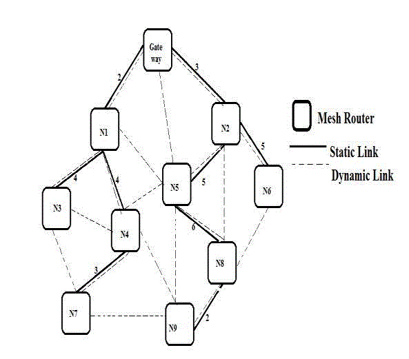
| Fig 1 shows the room structure at the end of construction of walls and before constructing the roof. |
 |
| A. Outer Wall Building Systems: |
| In Saudi Arabia, cement-based materials are used for construction of buildings, especially houses. Walls are of non-bearing walls type. Following are the most common wall construction methods (building systems): |
| 1) Single Wall |
| This is usually a 20-cm thickness wall using hollow building blocks. The blocks are either of red or cement type with surface dimensions of 60x20 cm2. There is a general notion among people, including construction contractors and even some engineers that red blocks are “good” insulators by themselves without insulation materials. Almost two decades ago, a new type of insulated block was introduced in the local market. The block width is 20 cm. This block is composed of a 7.5 cm polystyrene insulation material sandwiched between two hollow blocks of thickness 15 and 10 cm. |
| 2) Composite Wall |
| This is used when thermal insulation material such as polystyrene or rock wool is used to insulate the wall. The insulation material is used on the inside, outside or in the middle of the wall. Three walls of the test room are used for the comparative study. The walls are facing north, east and west. The fourth wall, facing south, is left for future studies. Each wall is composed of a number of building system modules. Following are description of the modules of each wall. |
| B. North Wall |
| Here we have four building system modules, shown in Fig. 2, described as follows: |
 |
| 1) A 20 cm Hollow Cement Block Single Wall. |
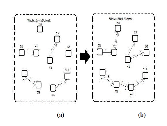
| The outside wall of some buildings, especially, old ones were built using this system of building. Of course its thermal insulation is poor. Fig 3 shows top view of the module. |
 |
| 2) A 30 cm Thickness Adobe Wall |
| The module was built using solid adobe (clay) bricks which has dimensions 20x30x10 cm3.The adobe material is made from locally available material. This type of building system was used traditionally in Saudi Arabia before the introduction of cement to the local building system. It is commonly believed here that adobe material has “very good” insulation characteristics. There is a tendency for revival of using this material in buildings. Fig 4 shows top view of the module. |
| 3) A 30 cm thick Composite Wall of Hollow Concrete Blocks with Insulation in the Middle This wall is composed of an inside 10-cm hollow concrete block, a 5-cm thickness polystyrene insulation material followed by an outside 15-cm hollow concrete block. Fig 5 shows top view of the module. |
| 4) A 20 cm thick Hollow Red Block Wall It is commonly believed that red hollow blocks has good thermal insulation characteristics. Fig 6 shows top view of the module. |
| C. East wall |
| This wall consists of five modules, as follows. |
| 1) A 30-cm thickness Composite wall of Hollow Concrete Blocks with Insulation in the Middle with façade glazing. This wall is made of an outer 15 cm thick concrete block, a central insulation layer of thickness 5 cm and a inner 10 cm layer of concrete block .Some architects may choose to add façade glazing to some of the exterior walls. The architects may decide to insulate the exterior wall, using the most common method of wall insulation. The glass even with a low transmissivity creates a heat trap between the glass and the wall which leads to increase in localized ambient temperature. Thus more heat would flow across the wall to the inside. Fig 7 shows top view of the module. |
| 2) A 20-cm Hollow Concrete Block Single Wall with Glazing Façade. This type of building system is being used when exterior renovation is used for existing old buildings without applying thermal insulation. Glazing façade is applied on the exterior surface of the wall. |
| 3) A 20-cm Hollow Red Block with Thermal Insulation Inserted in the Rectangular Spaces This is a step of improvement of thermal performance of red brick. Thermal insulation is not continuous, as shown in figure 8. |
| 4) A 30-cm thickness Composite wall of red Hollow Blocks with Insulation in the Middle This wall has an outer 15 cm red hollow brick layer, a central 5 cm insulation layer and an inner 10 cm red brick layer. The module structure is similar to that of section B.3but using red hollow blocks instead of concrete blocks. |
| 5) A 30 cm Thickness Composite Wall of Hollow Concrete Blocks with Insulation in the Middle This is exactly the same as module in section B.3 repeated here for comparison with other modules for the east wall. This building structure is the most popular type because it provides practical protection of the thermal insulation material. |
| D. West Wall |
| This wall consists of five modules as follows: |
| 1) A 30-cm thickness Composite wall of Hollow Concrete Blocks with Insulation in the Middle This is exactly the same as module in section B.3 repeated here for comparison with other modules of the west wall. |
| 2) A 20-cm Thickness Insulated concrete Blocks This type of blocks is casted while the thermal insulation material is present in the mold. This is one piece insulated block, where the insulation is continuous .However; during construction mortar is added between blocks. i, e, sides, top and bottom. The mortar thus creates thermal bridges. Fig 9 shows top view of the module. |
| 3) A 30 cm Thickness Composite Wall of Hollow Concrete Blocks with Insulation on the Exterior wall This wall has 25 cm of concrete block and 5 cm of insulation on the outside. This wall structure is similar to module in section B.3 except that the thermal insulation is situated on the outside surface instead of the middle of the wall. It is meant here to compare its performance with that of the same composite wall but with insulation in the middle of the wall. Fig 10 shows top view of the module. |
| 4) A 30 cm Thickness Composite wall of hollow Concrete Blocks with Insulation on the Interior Surface This wall structure is similar to module section B.3 except that the thermal insulation is situated on the inside surface instead of the middle of the wall. |
| It is meant here to compare its performance with that of the same composite wall but with insulation in the middle of the wall. Fig 11 shows top view of the module. |
| 5) A 28 cm Composite Wall |
| This wall consists of a 20-cm thickness concrete block, a 5-cm thickness polystyrene and a 3-cm gypsum board. This structure is used when old buildings are renovated to insulate the exterior walls. |
III. MONITORING OF THERMAL PERFORMANCE OF THE WALL MODULES |
| A. Measurement of Heat Flux through the Wall |
| Heat flux sensor (HF-4) made by Omega Inc., USA, is being used here to measure heat flow through the wall. Two sensors are placed on the inside surface of the wall at two different levels, as shown in Fig. 12, using epoxy paste which has high thermal conductivity. The mean value of the heat flux is considered to be the effective heat flux through the wall. |
 |
| B. Temperature Measurements |
| Thermocouples of type K, made by Omega Inc., USA, are being used here to measure temperature. Inside and outside wall surface temperatures are measured using two thermocouples on each side of the wall, as shown in Fig.13 at two different levels. Atmospheric and inside room air temperatures are also measured. Thermocouples are attached to wall surface using epoxy. |
 |
| C. Data Acquisition System |
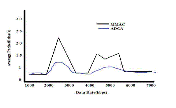
| The detailed instrumentation diagram is available in the appendix. The signal starts from a thermocouple or a heat flux sensor. It is received by the data acquisition system (DAS). It is then directed to the computer storage. Each data acquisition system OMB-DAQ-PDQ pair is capable of receiving 30 differential inputs or thermocouples. Since, presently 14 types of wall systems are to be measured, each with 4 thermocouples and 2 heat flux sensors, 84 differential input points are needed for the wall measurements. In addition to these 4 room temperature measurements and 2 outside temperature measurements are to be made. This brings the required number of OMBDAQ- PDQ pairs to 3. The three data acquisition systems are connected to a USB hub by data cables which in turn are connected to the computer for recording the measurements. The nomenclature used is as follows: T21 represents the outer wall thermocouple in the lower level (level 2) attached with wall system number 1 and t112 represents the inner wall thermocouple in upper lever (level 1) attached with wall stem number 12. All the heat flux sensors are placed inside the room and h18 represent the heat flux sensor at level 1 attached to wall number 8. |
IV. COMPARATIVE STUDIES |
| The building modules of each wall are subjected to the same outside and inside conditions. Thus its thermal performance would reflect its characteristics. The exterior surface of all walls is white painted. The test room is air conditioned by two wall mounted split units each with a cooling capacity of 1.5 ton of refrigeration. The comparative study is planned to cover the following indicative parameters: |
| 4.1 Module inside surface temperature. |
| 4.2 Rate of heat transfer through the module |
| 4.3 Instantaneous effective thermal resistance of the modules |
V. CONCLUSION |
| A wall system that includes different combinations of building walls where each wall system represents an actual exterior wall used in practice was designed and constructed. The instrumentation for detailed measurement of the thermal performance of the different wall systems was set up. This constitutes the first phase of the project. It is proposed to conduct data acquisition and analysis of the results in the second phase. |
VI. ACKNOWLEDGEMENT |
| This work is a part of the project number 08-ene-376-02. The authors would like to acknowledge the financial support of NPST at King Saud University and the support of Dr.Samy Ali Al-Sanea, the Principal Investigator of the project. |
APPENDIX |
| Instrumentation layout for the test room |
 |
References |
|