ISSN ONLINE(2319-8753)PRINT(2347-6710)
ISSN ONLINE(2319-8753)PRINT(2347-6710)
S. R. Patel1, Dr. A. A. Shaikh2
|
| Related article at Pubmed, Scholar Google |
Visit for more related articles at International Journal of Innovative Research in Science, Engineering and Technology
A state of the art in unconventional machining is the use of high pressure waterjet as cutting tool. Abrasive is mixed to such high pressure pure waterjet to attain abrasive waterjet to increase its cutting capability many times and can almost any material. Abrasive waterjet machining is a versatile process and widely being used for cutting profiles from various materials. The abrasive in the water jet would provide numerous cutting edges to increase its cutting potential many folds. Evidently the increased cutting capability would depend upon the amount and type of abrasive blended in to the abrasive waterjet. Therefore, the flow rate of the abrasive becomes very important machine parameter that could be adjusted to control the machining performance of the abrasive waterjet. To study the influence of the abrasive flow rate on machining performance experimentally, accurate control and measurement is called for. This paper presents an attempt for the calibration of abrasive flow control system mounted on an Abrasive Waterjet Machine intended to perform research oriented experiments.
Keywords |
| Waterjet, Abrasive, Abrasive Waterjet, Abrasive flow rate (AFR), Calibration |
INTRODUCTION |
| Abrasive waterjet machining is an unconventional machining process that uses erosive effect of high velocity water jet mixed with abrasive for profile cutting and being used successfully for milling & carving 3D contours as well. Other than cutting, pure waterjet and abrasive waterjet have been employed for paint removal, cleaning, surgery, peening, and numerous different applications. This is a versatile machining technology and the advantages over most other machining processes performing same operation are; (i) it can cut intricate profiles out of any material; from thin foils up to thick slabs with the accuracy and precision of the CNC positioning system, (ii) it leaves small kerf width, nearly equals jet diameter makes it possible to use tight nesting for optimal material usage, (iii) it does not require additional/special tooling, so saves on tool changing time and inventory, (iv) it can ensues almost burr free cutting and with appropriate setting of parameters, gives good surface finish that might not require secondary operation, (v) it has very low cutting forces in jet direction and lesser in other directions requires minimum clamping, (vi) inherently cool cutting, hence no heat affected zone (HAZ), very important for heat sensitive material, (vii) it tend to be ‘Environment friendly’ since water carry away the debris (and fumes in case of plastics) of cutting, (viii) it is superior process in terms of productivity due to faster rate of cutting minimal change over time etc. [1-11] The idea of machining with waterjet (WJ) is adopted from nature that has been showing phenomena of erosion of hardest of the rock by a stream of water. The rate of erosion is observed to be faster when the water stream is mixed with sand particles and that has lead to the development of abrasive waterjet (AWJ) technology. High velocity waterjet is created by passing high pressure water through a very small orifice while the abrasive is added to it in a so called mixing chamber to generate Abrasive Waterjet. These added cutting edges provided by abrasive particles increase the cutting capability of abrasive waterjet many times more than pure waterjet. This enhancement can be related to the abrasive flow rate along with abrasive types in terms of shape, size and hardness. Once the abrasive type is selected, the flow rate of the abrasive would become an important parameter that affects the machining performance in terms of cutting speed as well as kerf quality. Therefore to perform experimental work to study the relationship between abrasive flow rate and cutting performance as single factor or in combination with other affecting machine parameters, accurate measurement and control of abrasive flow would be very important. Hence it would require calibration of the abrasive supplying system in terms of control adjustment vs. abrasive mass flow rate. Since the machine being considered is not installed with any dedicated abrasive flow measuring system, the calibration was carried out using fundamental technique of flow measurement. [12-14] |
THE ABRASIVE WATERJET MACHINE AND ABRASIVE FLOW CONTROL SYSTEM |
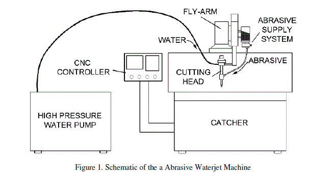
| Abrasive waterjet machine tool to be employed for the experimental work is shown schematically with major components in Figure 1. Pure water is pumped to very high pressure (200 - 300 MPa) and made to pass through an orifice of very small diameter (0.2 - 0.3 mm), then mixing chamber and outlet nozzle of relatively larger diameter ( 0.7- 0.8 mm) enclosed in a module called cutting head having other necessary components. It is mounted on fly arm of a computer numerical control (CNC) positioning and motion system along with abrasive supply system. |
 |
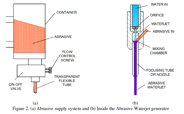
| The major components of abrasive supplying system and abrasive water jet converter to be calibrated are schematically depicted in Figure. 2(a) and 2(b). |
 |
| The abrasive flow rate entering mixing chamber due to gravity is controlled in on-off mode by pneumatically operated valve while abrasive flow control is achieved by turning the control screw provided. This valve also has pneumatically operated built-in anti-clogging device. Applying Bernoulli's theorem at the orifice of the cutting head neglecting friction; |
 |
| Where; p1, v1 , ρ1, z1 and p2, v2 , ρ2, z2 are the pressure, velocity, density and height at the entry and the exit of the orifice respectively and g is the acceleration due to gravity in appropriate units. |
| For this case, fluid being water and very small thickness of orifice, practically ρ1= ρ2 , and z1ïÃâû z2 . From equation (1), with p1 >> p2 , v2 >> v1 , i.e., since the pressure before the orifice is very high compared to orifice exit being atmospheric there will be tremendous rise in the velocity of the water at the exit of the orifice to induce negative pressure or partial vacuum in the mixing chamber. This vacuum induced will draw the mixture of air and abrasive from the abrasive container through transparent flexible tube to get mixed with water. Thus, the jet coming out of nozzle will be actually having lesser velocity than pure water jet for this three phase flow comprising of water, abrasive and air than pure waterjet. It could be shown that the abrasive flow to the mixing chamber is primarily due to gravity and further increased by the vacuum in the mixing chamber. Hence the abrasive flow rate in abrasive waterjet depends on the upstream hydraulic pressure. From the construction of the abrasive flow control valve, the function of the control screw seems to break or reduce the amount vacuum in the mixing chamber and thereby decrease the abrasive flow. Thus, it can be deduced that for the vacuum created for a particular setting of hydraulic pressure, the abrasive flow rate would be maximum when screw is fully closed or maximum possible vacuum in the mixing chamber. On the contrary, minimum abrasive flow would occur when the control screw is fully open causing minimum vacuum in the mixing chamber. Further, it can be said that the abrasive flow at any given moment will depend on the height of the abrasive stored in the container, clarity of all the passages along with constrictions and the constancy in the mixing ratio of water, air and abrasive in the mixing chamber. |
THE MEASUREMENT OF ABRASIVE FLOW RATE |
| The fundamental technique of measurement of flow rate is to measure the volume of the substance collected at the outlet in unit time. [15-16] Since it is quite difficult to collect the abrasive coming out of the nozzle due to the very powerful abrasive waterjet, the abrasive going out of the container was measured by measuring change in the volume of the abrasive in the container per unit time. The reduction in the volume of abrasive in the cylindrical container was determined by measuring the reduction in the level of abrasive with reference to a scale pasted on the container for a fixed interval of time. The volume flow rate of abrasive may be given as; |
 |
| Where; |
| A = Cross section area of the abrasive container in mm2 |
| hi = initial level of abrasive in the container in mm |
| hf = final level of abrasive in the container in mm |
| t = interval of time in minutes for which the abrasive waterjet run was kept on levels are measured. |
| For the units of abrasive flow rate to be in g/min, the apparent density of abrasive would be needed. This was determined by measuring weight of the abrasive for a fixed volume of abrasive filled in a container on a digital weighing balance. The bulk or apparent density of the abrasive may be computed using; |
 |
| Where; |
| W = weight of the abrasive filled in a container of known volume in gm (grams) |
| B = volume of the measuring jar in mm3 |
| Therefore the flow rate of abrasive in gm/min would be; |
| The trials were carried for setting pressure from 48 to 120 MPa in steps of 24 MPa and opening control screw from 1 to 8 turns from fully closed (0 turns) in steps of 1 turn with each combination replicated thrice. It was found that the cross section of container holding abrasive to be 221.63 cm2 for average internal diameter and the bulk density of abrasive to be 2.1 g/cm3. Different pressures on the hydraulic pump were set by pressure setting screw provided in pump and the abrasive flow control screw was scribed with mark when it was completely closed and same mark was used for other setting. |
| A. The Outcome of the Calibration |
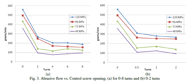
| The calculated flow rate of abrasive using the data and pertinent equations is arranged in Table1. Same data is presented as line chart in Figure 3(a) using 0-8 turns in steps of two turns while chart in the Figure 3(b) reveals the characteristics between 0 to 2 turns. The data points for 0.5 turns and 1 turns were taken after completion of experiments and analysis of the results for 0-8 turns because it was felt that the characteristics of calibration curve between 0-2 turns should also be understood. |
 |
| The maximum abrasive mass flow rate occurred at fully closed position of the control screw and dropped to minimum flow rate when the control screw is opened just half a turn. Then it remained almost same with some variation for the rest of the position of control screw, i.e. it is unwounded up to eight turns. It can also be noted that the flow rate is maximum when water pressure is set to maximum for the selected settings of pressure values as anticipated. The mass flow rates of the abrasive vary randomly but within a range after one turn of screw opening. |
CONCLUSION |
| The experimental data collected for the calibration indicate that the effect of abrasive flow control screw position the machine under study may have significant effect only up to about half the turn of opening from fully closed position, out of possible about eight turns of opening. Thus, the effectiveness of the control screw for the flow of abrasive is very limited and to set the screw for a fraction of a turn accurately would surely bring uncertainty in the experimentation. Therefore it would be extremely difficult to control abrasive flow rate with desired accuracy and repeatability in the system studied. Based on the understanding developed on working of the abrasive flow control system and its actual behavior of the system studied, it could be possible to modify the existing or develop a new abrasive flow control system for the accurate control of the abrasive flow with desired characteristics for the research work to study effect of abrasive flow rate along with other abrasive waterjet parameters. |
ACKNOWLEDGMENT |
| The author gratefully acknowledges help and courtesy of Mr. Jignesh Patel – Ph.D. student, Mr. Ankush Sharma – M.Tech. sudent and Mr. Gajendra Panchal – Mechanical Workshop of Sardar Vallabhbhai National Institute of Technology for carrying out the work presented here. |
References |
|