ISSN ONLINE(2319-8753)PRINT(2347-6710)
ISSN ONLINE(2319-8753)PRINT(2347-6710)
B.Sangeetha 1, Raji PanduRangan 2, Dr.V.U.Kiran Kumar 3
|
| Related article at Pubmed, Scholar Google |
Visit for more related articles at International Journal of Innovative Research in Science, Engineering and Technology
In this paper, we proposed a new data-gathering mechanism for large-scale wireless sensor networks by introducing mobility into the network. A mobile data collector, for convenience called an M-collector in this paper, could be a mobile robot or a vehicle equipped with a powerful transceiver and battery, working like a mobile base station and gathering data while moving through the field. An M-collector starts the data-gathering tour periodically from the static data sink, polls each sensor while traversing its transmission range, then directly collects data from the sensor in single-hop communications, and finally transports the data to the static sink. Since data packets are directly gathered without relays and collisions, the lifetime of sensors is expected to be prolonged. In this paper, we mainly focus on the problem of minimizing the length of each data-gathering tour and refer to this as the single-hop datagathering problem (SHDGP).
Keywords |
| M-Collector; Mobile Robot; Single – hop data – gathering problem; Wireless sensor nodes. |
I. INTRODUCTION |
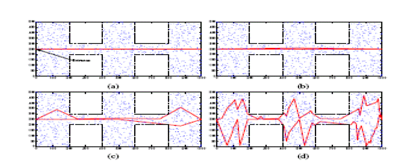
| This paper describes a new data-gathering mechanism for large scale sensor networks when single or multiple Collectors are used. These also focuses on the problem of minimizing the length of each data-gathering tour and formulate it into a mixed-integer programming (MIP). In this paper we propose a spanning tree covering algorithm for the single M-collector case. We also consider utilizing multiple M-collectors and propose a data-gathering algorithm where multiple M collectors traverse through several shorter sub tours concurrently to satisfy the distance/time constraints. Extensive simulations are used for this purpose. |
| We first formalize the SHDGP into a mixed-integer program and then present a heuristic tour-planning algorithm for the case where a single M-collector is employed. Our single-hop mobile data gathering scheme can improve the scalability and balance the energy consumption among sensors. It can be used in both connected and disconnected networks. |
| The proposed data-gathering algorithm can greatly shorten the moving distance of the collectors compared with the covering line approximation algorithm and is close to the optimal algorithm for small networks. In addition, the proposed data-gathering scheme can significantly prolong the network lifetime compared with a network with static data sink or a network in which the mobile collector can only move along straight lines. An embedded system performs one or a few predefined tasks, usually with very specific requirements. |
II. RELATED WORK |
| The paper [1] presents role of wireless ad hoc networks in various applications. A key challenge in such networks is to achieve maximum lifetime for battery-powered mobile devices with dynamic energy-efficient algorithms. The paper [2] presents and analyses architecture to collect sensor data in sparse sensor networks. Our approach exploits the presence of mobile entities (called MULEs) present in the environment. The paper [3] presents historically considered support of Wireless networks for mobile elements as an extra overhead. However, recent research has provided means by which network can take advantage of mobile elements. Particularly, in the case of wireless sensor networks, mobile elements are deliberately built into the system to improve the lifetime of the network, and act as mechanical carriers of data. The paper [4] presents traditional multi-hop routing in wireless sensor networks to report events to a sink node or base station will result in severe imbalanced energy consumption of static sensors. In addition, full connectivity among all the static sensors may not be possible in some cases since generally the sensors are randomly deployed in the target region. In previous generation there are wireless systems available for remote monitoring and gathering in the forest area, but the system made a restriction i.e. the user has to go near the node to gather the data in his PC. Later obtained value from the PC is given to the database section for planning. In this system the manual power is necessary. At present there are system which has wireless communication between the node and monitoring section. But it can transmit data to limited distance cause of the factor necessary of more power/100meter. Hence restriction in distance is occurred in this system. |
| The disadvantages of existing systems are |
| ïÃÆÃË The communication can be done to limited extend. |
| ïÃÆÃË Monitoring through PC from remote access is not possible |
| ïÃÆÃË Manual operation is not possible |
| As the existing system has the above mentioned drawback we need a system to overcome those drawbacks so we go for the proposed system. This system has modules like Zigbee which can transmit data few meters where we can monitor from remote place. |
III. PROPOSED SYSTEM BLOCK DIAGRAM |
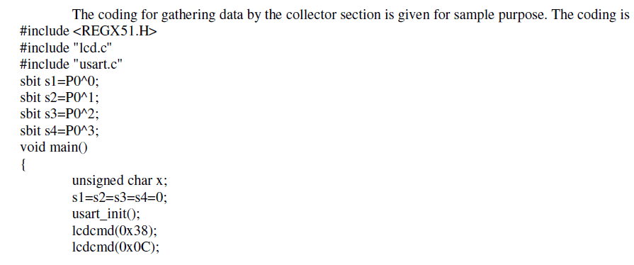
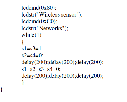
| This system has four sections. Two sections are node sections which have a microcontroller, Sensors, LCD display and Zigbee. The collector section has a robot and a Zigbee which will function as a inter-mediator between the nodes and the monitoring section. The monitoring section has PC and a Zigbee. The collector section is used here to collect the data from the nodes and it transmits to the monitoring section. This will increase the communication distance between Nodes and the monitoring section. Node 1 and Node 2 Zigbee transmit the temperature and humidity parameters. Robot section receives that parameter and transmits at long distance at low cost. Another ZigBee section receives the same parameter and monitor through the PC. |
| A liquid crystal display (LCD) is a flat panel display, electronic visual display, or video display that uses the light modulating properties of liquid crystals (LCs). LCDs do not emit light directly. Here the LCD is used to display the parameters like temperature and humidity. PC is used to store and update the details of the corresponding parameters. It will get the node 1 and node 2 parameters from the microcontroller and analyze it for further process. |
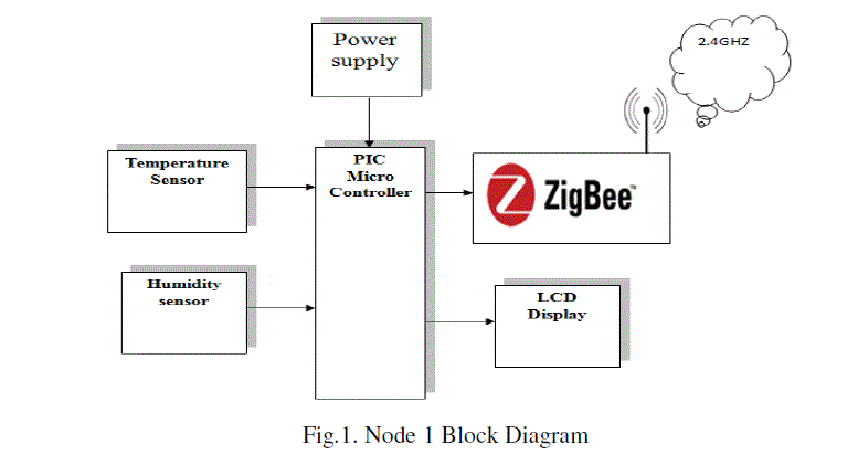 |
| Node 1 has a microcontroller, Sensors, LCD display and Zigbee. This node will transmit the data to collector section when it is come within this region. The temperature and humidity sensor senses the temperature and humidity of the surrounding region instantly. |
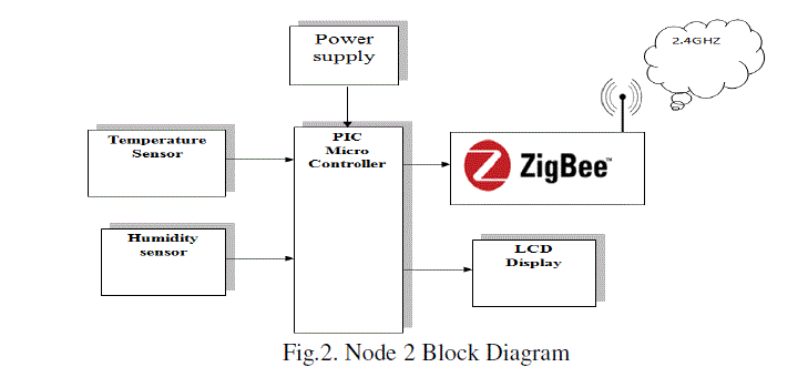 |
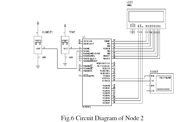
| Similarly, Node 2 has also a microcontroller, Sensors, LCD display and Zigbee. This node will transmit the data to collector section when it is come within this region. The temperature and humidity sensor senses the temperature and humidity of the surrounding region instantly. |
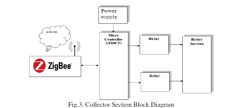 |
| Collector section has a microcontroller, power supply unit, relays, robot section and Zigbee. Here with the help of robot the collector section moves in allotted path. When this collector section comes within the node, it collects the temperature and humidity of that region through zigbee. |
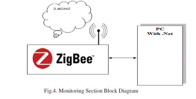 |
| Monitoring Section has zigbee with PC. Through monitoring section the observer can see the temperature and humidity of the particular nodes in sequence manner. |
IV. BLOCK DIAGRAM EXPLANATION |
| POWER SUPPLY UNIT - The system requires the power supply of 5V DC which is rectified from 230V AC supply. Firstly, the step down transformer used here is for converting the 230V AC into 12V AC. The bridge rectifier converts AC into DC supply. The output of the rectifier will have ripples so we are using the 2200uf capacitor for filtering those ripples. The output from the filter is given to the 7805 voltage regulator, which will convert the 12V DC into 5V DC. The output from the regulator will be filtered using the 1000μf capacitor, so the pure 5V DC is getting as the output from the power supply unit. |
| AT89C51 MICROCONTROLLER - A microcontroller (also microcontroller unit, MCU or μC) is a small computer on a single integrated circuit consisting of a relatively simple CPU combined with support functions such as a crystal oscillator, timers and etc. This microcontroller receives the data from ZigBee and transmits from the same ZigBee using Robot mechanism. |
| PIC16F877A MICROCONTROLLER - The PIC16F877A CMOS FLASH-based 8-bit microcontroller is upward compatible with the PIC16C5x, PIC12Cxxx and PIC16C7x devices. It features 200 ns instruction execution, 256 bytes of EEPROM data memory, self programming, an ICD, 2 Comparators, 8 channels of 10-bit Analog-to-Digital (A/D) converter, 2 capture/compare/PWM functions, a synchronous serial port that can be configured as either 3-wire SPI or 2-wire I2C bus, a USART, and a Parallel Slave Port. This microcontroller module monitors the temperature and humidity and send through the ZigBee module. |
| TEMPERATURE SENSOR - Temperature is the most-measured process variable in industrial automation. Most commonly, a temperature sensor is used to convert temperature value to an electrical value. Temperature Sensors are the key to read temperatures correctly and to control temperature in industrials applications. We in our project are using brushed DC Motor, which will operate in the ratings of 12v DC 0.6A which will drive the flywheels in order to make the robot move |
| HUMIDITY SENSOR- Hygrometers are instruments used for measuring relative humidity. A simple form of a hygrometer is specifically known as a psychomotor and consists of two thermometers, one of which includes a dry bulb and the other of which includes a bulb that is kept wet to measure wet-bulb temperature. Hair curvature is another old method of measuring humidity. Modern electronic devices use temperature of condensation, changes in electrical resistance, and changes in electrical capacitance to measure humidity changes.c |
| ZIGBEE MODULE - Node 1 and Node 2 Zigbee transmit the temperature and humidity parameters. Robot section receives that parameter and transmits at long distance at low cost. Another ZigBee section receives the same parameter and monitor through the PC. |
| LCD DISPLAY - A liquid crystal display is a flat panel display, electronic visual display, or video display that uses the light modulating properties of liquid crystals (LCs). LCDs do not emit light directly. Here the LCD is used to display the parameters like temperature and humidity. |
| PC, RELAY, DC MOTOR AND ROBOT - PC is used to store and update the details of the corresponding parameters. It will get the node 1 and node 2 parameters from the microcontroller and analyze it for further process. Relay unit drives the robot module. Robot unit have a ZigBee receive from varies node parameter and transmit to pc. In this project, brushed DC Motor is used, which will operate in the ratings of 12v DC 0.6A which will drive the flywheels in order to make the robot move. |
V. HARDWARE IMPLEMENTATION |
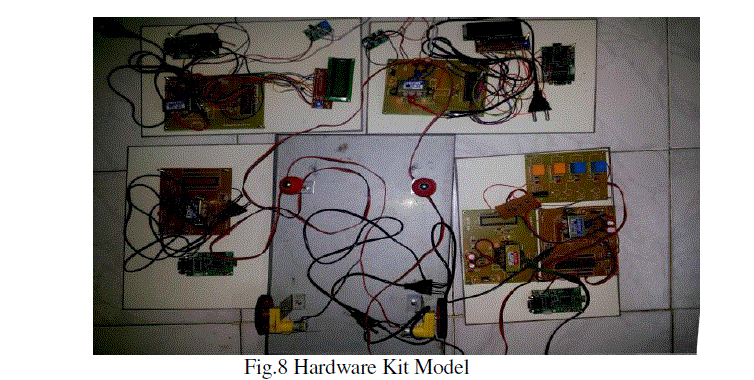
| This system has four sections. Two sections are node sections which have a microcontroller, Sensors, LCD display and Zigbee. The collector section has a robot and a Zigbee which will function as a inter-mediator between the nodes and the monitoring section. The monitoring section has PC and a Zigbee. The collector section is used here to collect the data from the nodes and it transmits to the monitoring section. This will increase the communication distance between Nodes and the monitoring section. |
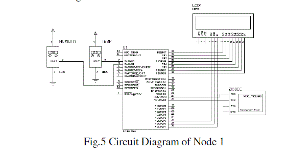 |
| Node 1 and Node 2 Zigbee transmit the temperature and humidity parameters. Robot section receives that parameter and transmits at long distance at low cost. Another ZigBee section receives the same parameter and monitor through the PC. The power supply unit (PSU) gives +5V power supply to the microcontroller unit to do its operation. In the same way, it also gives +12V power supply to the relay and DC motor to do its operation. |
 |
| The liquid crystal display (LCD) is a flat panel display, electronic visual display, or video display that uses the light modulating properties of liquid crystals (LCs). LCDs do not emit light directly. Here the LCD is used to display the parameters like temperature and humidity. PC is used to store and update the details of the corresponding parameters. It will get the node 1 and node 2 parameters from the microcontroller and analyze it for further process. |
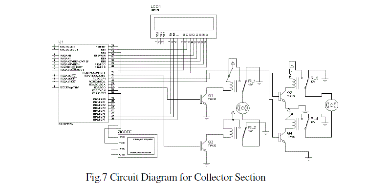 |
| PC is used to store and update the details of the corresponding parameters. It will get the node 1 and node 2 parameters from the microcontroller and analyze it for further process. Relay unit drives the robot module. Robot unit have a ZigBee receive from varies node parameter and transmit to PC. The Robot can move to and fro by keeping 12V DC motor as axis in the front wheel of the Robot. |
 |
V. SIMULATION RESULTS |
 |
 |
 |
VI. CONCLUSION |
| In this paper, we proposed a mobile data-gathering scheme for large-scale sensor networks. We introduced a mobile data collector, called an M-collector, which works like a mobile base station in the network. An M-collector starts the data gathering tour periodically from the static data sink, traverses the entire sensor network, polls sensors and gathers the data from sensors one by one, and finally returns and uploads data to the data sink. Our mobile datagathering scheme improves the scalability and solves intrinsic problems of large-scale homogeneous networks. |
| Future work will include a comparative study between the proposed system and other wireless system, focusing on energy efficiency and maintenance costs. We will take also into consideration the higher flexibility of wireless systems against wired systems. Further implementations will be done in order to extend the proposed system to other standards or technologies of Guidance, luminaries or lightning communication and control protocols. Finally, the application or User Interface may be developed in deep in order to support functionality for Wireless communication pursuing also the improvement of the user experience. |
References |
|