ISSN ONLINE(2319-8753)PRINT(2347-6710)
ISSN ONLINE(2319-8753)PRINT(2347-6710)
Vinod S. Muchchandi1, S. C. Pilli2
|
| Related article at Pubmed, Scholar Google |
Visit for more related articles at International Journal of Innovative Research in Science, Engineering and Technology
Vertical tail and the rudder are important structural components of an aircraft. Movement of the rudder controls the yawing of an aircraft. Structurally speaking vertical tail is a typical mini-wing construction. A major difference could be absence of ribs and multiple spars (more than 2) in the vertical tail construction. Vertical tails have symmetrical airfoil cross sections. Therefore in the absence of rudder deflection there is no aerodynamic load acting on the fuselage. However significant side loads develop due to rudder deflection and this is the major design load for the vertical tail. For transport aircraft side gust load is also important from a design point of view. In this project a typical spar of a vertical tail of a transport aircraft will be analysed. Loads representative of a small transport aircraft will be considered in this study. An efficient tapered spar beam will be designed for this load. SOM approach will be used for preliminary sizing of the spar. This will be followed by FEA for a more accurate stress analysis that will be used to improve the design.
Keywords |
| Transport aircraft, Vertical tail, Spar, Symmetrical aerofoil, Side load, SOM, FEM |
INTRODUCTION |
| An aircraft is a complex structure, but a very efficient man-made flying machine. Air-craft structure is the most obvious example where functional requirements demand light weight and stronger structures. An efficient structural component must have three primary attributes, namely, 1) The ability to perform its intended function, 2) Adequate service life and 3) With the capability of being produced at reasonable cost. The primary factors to consider in aircraft structures are strength, weight, and reliability. These factors determine the requirements to be met by any material used to construct or repair the aircraft. Airframes must be strong and light in weight. All materials used to construct an aircraft must be reliable. Reliability minimizes the possibility of unexpected failures. The major part of the aircraft structure consists of built-up panels of sheets and stringers, e.g. wing and fuselage skin panels, spar webs and stiffeners. Airframes are members and transverse frames to enable it to resist bending, compressive and vehicles which are able to y by being supported by the air, or in general, the atmosphere of a planet. An aircraft counters the force of gravity by using either static lift or by using the dynamic lift of an airfoil, or in a few cases the downward thrust from jet engines. Aircrafts are generally built-up from the basic components of fuselage, wings, tail units and control surfaces. Each component has one or more specific functions and must be designed to ensure that it can carry out these functions reliably. Any small malfunction or failure of any of these components may lead to a catastrophic disaster causing huge destruction of lives and property. When designing an aircraft, it's all about ending with the optimal proportion of the weight of the vehicle and payload. It needs to be strong and sti enough to withstand the exceptional environment in which it has to operate. Durability is also an important factor. Also, if a part fails, must not necessarily result in failure of the whole aircraft. It is still possible for the aircraft to glide over to a safe landing place only if the aerodynamic shape is retained and structural integrity is achieved. |
II. SOFTWARE DESCRIPTION |
| Software's used in the present work are 1. Finite element modeling (PATRAN) A finite element pre and post processors (such as MSC/PATRAN) is a graphicbased software package primarily designed to aid in the development of Finite Element Model (Pre processing) and to aid the display and interpretation of analysisresults (Post processing). MSC/ PATRAN software is a mechanical Computer AidedEngineering Design. Utilizing integrated automatic technologies.It enables design engineers to build and modify solid models of computer partsand predicts their behavior through design optimization. In addition preprocessingsoftware helps the analyst modify the model if the result shows that changes andsubsequent reanalysis are required. 2. Finite element solver [NASTRAN] The nite element method has a seminal impact on the eld of analysis and design. This technique has allowed thing solution of a new class of problem that is practically dicult, costly or was not possible in the past. The acceptance of FEM in the industry however did not enjoy wide popularity until the acceptance of general purpose programs nite element programs. |
III. DESIGN AND ANALYSIS OF SPAR BEAM |
| 1. Stress Comparison with Different Cross Sections Considering the cantilever beam of 500 mm length and 350 kg load. The deformationand stress for di_erent cross section considered and compared on Table 5.1. |
 |
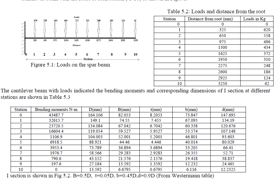
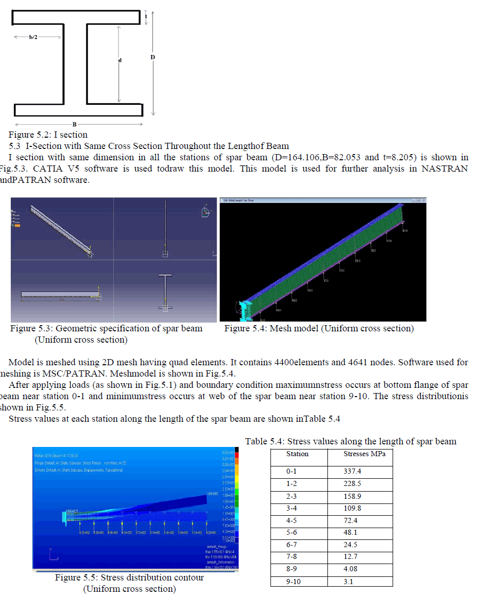
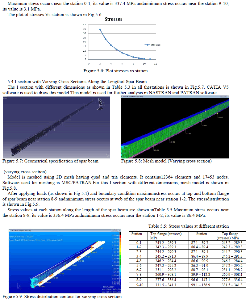
| The above values show that the I section experiences the least amount of stressfor the given type of loading similar to the loads on the aircraft. This is becausethe I-section has two anges which take the drag load and a web supported by theanges which takes the sideward bending type of loads. Thus for a given strengthto weight ratio criteria the I-section withstands more loads comparatively. Henceconsidering all these criteria spar of I section is used in design. 2. Design Optimization of Spar Beam ïÃâ÷ I-section with same cross section throughout. ïÃâ÷ I-section with varying cross sections along the length. ïÃâ÷ I-section of varying cross section with cutouts. 3. Problem Definition of Spar Beam Cantilever beam having length of 3250 mm and loads (62-620 Kg) as shown inTable and Fig. Its Ultimate strength is 343.35 MPa (From Westerman table) Cantilever beam with the loads at each station ( 1-10) as shown in Fig.5.1. |
 |
 |
 |
IV. SHAPE OPTIMISATION |
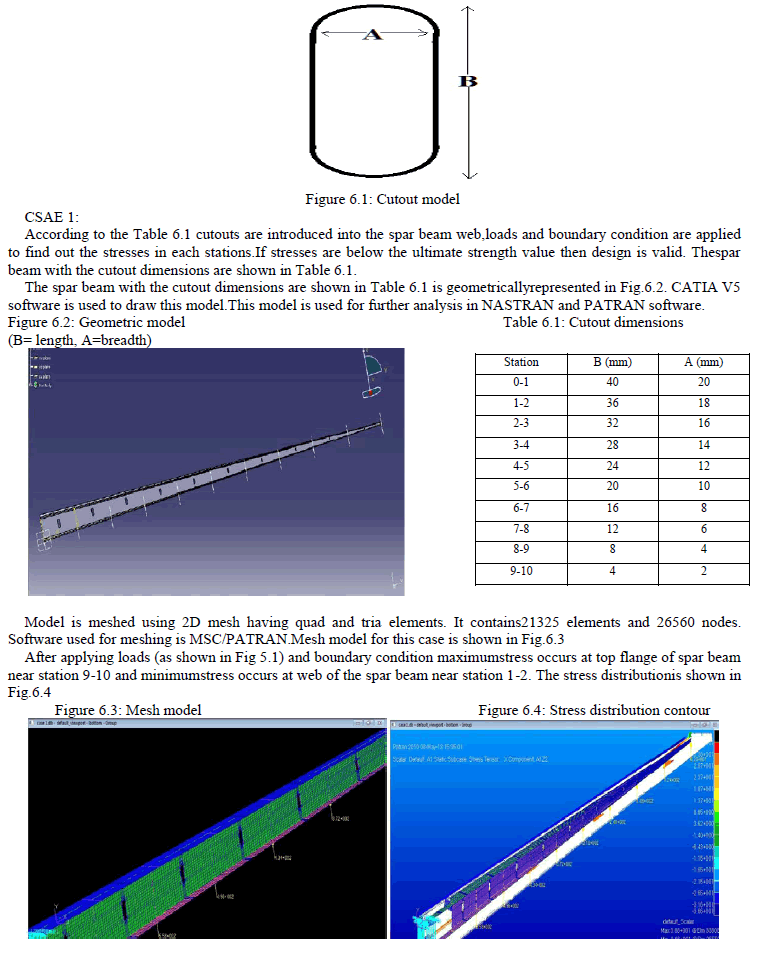
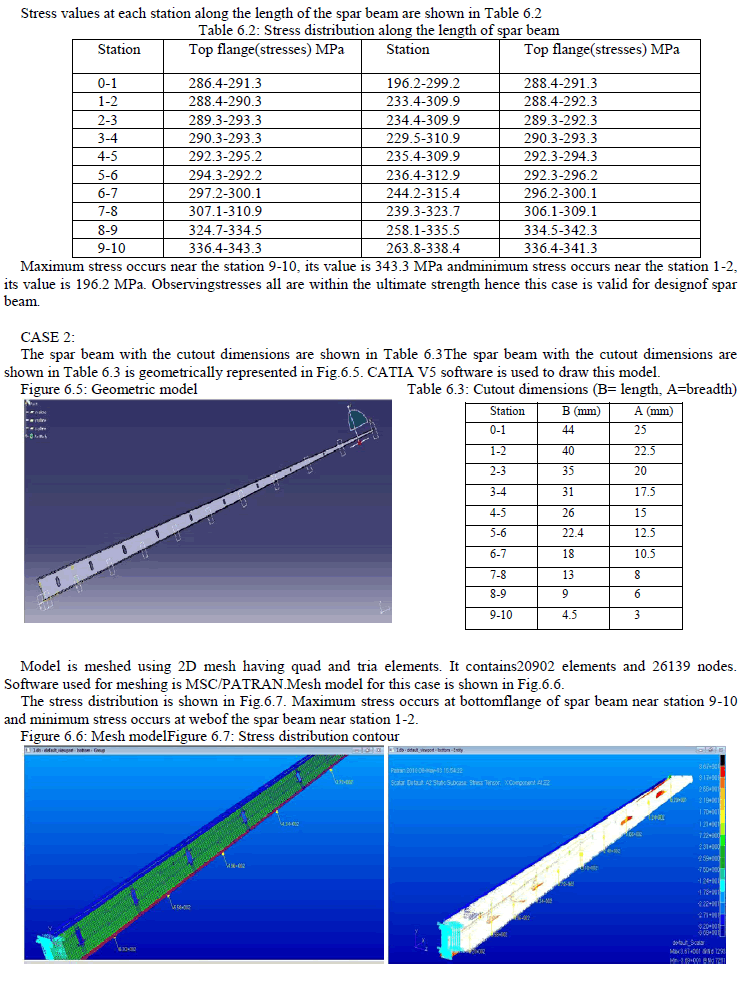
| The beam with varying section has been divided into six cases for the analysis,having varying cutout dimensions at each station. The schematic cutoutdimensions are shown in Fig.6.1 |
 |
 |
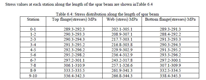 |
| Maximum stress occurs near the station 9-10, its value is 345.3 MPa andminimum stress occurs near the station 1-2, its value is 202.1 MPa. Observingstresses all are within the ultimate strength hence this case is valid for designof spar beam. |
CONCLUSIONS |
| The present work illustrates how stress analysis can be used in the designof aircraft components. The technology has been successfully used in an industrialenvironment within short span of time and it is proved to be able toprovide efficient component designs as this eliminates actual prototypes foranalysis. However for better results the detailed test has to be carried out. The objective of the present study is to investigate the stresses acting in thespar beam of the vertical tail with and without cutouts. The analysis shows thatincrease in the air drag load increases the maximum stress. The differential airdrag load is applied between the range 62 to 620 Kg which varies non-linearly.In this study, the effects of stresses in aircraft spar beam structure with andwithout cutouts are determined. A typical spar beam with and without cutoutsof standard configurations is loaded and analysed. Parametric studies weredone to examine the effects of different cutouts.Based on the results of finiteelement predictions and by the calculations of the stress analysis approach, itis apparent that the air drag load has more effect on the top and bottom flange.From the load cases the maximum stress is compared with yield stress andultimate stress of 2024 T351 aluminum alloy. The obtained magnitudes ofmaximum stress are less than the yield stress and ultimate stress so we concludethat material in elastic limit and not yet started yielding. In the project work the following is carried out, 1. The standard dimensioned spar beam is considered for the stress analysis. 2. Finite element approach is used for the stress analysis. 3. Typical air drag load of non linear type is considered for loading. 4. The effects of the air drag load and the rudder loads have been studied bymeans of models of increasing geometrical complexity of vertical tail segment. 5. Higher mesh density with good quality of elements is used for finiteelement modeling. 6. Loads and boundary conditions are accurately simulated to obtain therealistic loading conditions. 7. Maximum stress is observed at bottom flange segment near cutout edges. |
References |
|