ISSN ONLINE(2278-8875) PRINT (2320-3765)
ISSN ONLINE(2278-8875) PRINT (2320-3765)
Siny Paul1, Neethu M T2, Nidhun Das P3, Nishin Antony4, Nithin Xavier5
|
| Related article at Pubmed, Scholar Google |
Visit for more related articles at International Journal of Advanced Research in Electrical, Electronics and Instrumentation Engineering
Obstruction detection robot always tries to avoid obstructions in front of it. It uses Atmega 16a. It has four i/o ports. It automatically sense at how much is the obstruction. According to the distance calculated it directs the actuators to move in appropriate direction. The robot continuously emits infrared rays. It reflect back when it strikes on obstruction. The reflected IR beam is received by the IR receiver. According to the intensity of IR received the distance is calculated. If this is above a threshold value, then microcontroller sense this and directs the motors accordingly. There by it avoids the obstruction in front of it. The circuit finds variety of applications in our day to day life. It varies from robotics to games. These types of robots are also used in defense systems to track and detect explosives and also to diffuse them.
Keywords |
| Atmega 16a, L293D, ADC |
INTRODUCTION |
| Automatic systems and machines are becoming very popular now. The new technology has introduced automatic car parking systems to more complex auto pilot systems to us. The basic principle of all these systems is that, they continuously check and monitor the surrounding conditions. According to conditions, changes are made by the system program. |
| The same principle is used by the obstruction detection robot. In order to monitor the atmospheric conditions the system continuously emit infrared waves to the atmosphere. The heart and brain of the system is the microcontroller ATmega 16a. The device is manufactured using Atmel’s high density non volatile memory technology. The on chip ISP flash allows the program memory to be reprogrammed in-system through an SPI serial interface, by a conventional non volatile memory programmer, or by an on chip boot program running on the AVR core. It has four i/o ports and 8 ADC channel. This microcontroller direct the motor using motor driver IC L293D according to the intensity of IR received. There by avoid the obstruction. |
ATMEGA 16A |
| The Atmega16a is a low-power CMOS 8-bit microcontroller based on the AVR enhanced RISC architecture. The Atmega328P provides the following features: 32K bytes of In-System Programmable Flash with Read-While-Write capabilities, 1K bytes EEPROM, 2K bytes SRAM, 23 general purpose I/O lines, 32 general purpose working registers, three flexible Timer/Counters with compare modes, internal and external interrupts, a serial programmable USART, a byte oriented 2-wire Serial Interface, an SPI serial port, a 6-channel 10-bit ADC (8 channels in TQFP and QFN/MLF packages), a programmable Watchdog Timer with internal Oscillator, and five software selectable power saving modes. The Idle mode stops the CPU while allowing the SRAM, Timer/Counters, USART, 2-wire Serial Interface, SPI port, and interrupt system to continue functioning. The Power-down mode saves the register contents but freezes the Oscillator, disabling all other chip functions until the next interrupt or hardware reset. In Power-save mode, the asynchronous timer continues to run, allowing the user to maintain a timer base while the rest of the device is sleeping. The ADC Noise Reduction mode stops the CPU and all I/O modules except asynchronous timer and ADC, to minimize switching noise during ADC conversions. In Standby mode, the crystal/resonator Oscillator is running while the rest of the device is sleeping. This allows very fast start-up combined with low power consumption. |
WORKING AND CIRCUIT DIAGRAM |
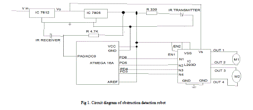
| The obstruction detection robot always tries to avoid the obstruction in front of it. Circuit consists of IR transmitter, IR receiver, microcontroller Atmega 16a, motor driver L293D. An IR LED, also known as IR transmitter, is a special purpose LED that transmits infrared rays in the range of 760nm wave length. Such LEDs are usually made of Gallium Arsenide or Aluminum Gallium Arsenide. They along with IR receivers are commonly used as sensors. IR receiver has all the filtering and 38kHz demodulation |
 |
| Fig 1. Circuit diagram of obstruction detection robot |
| built into the unit. Infrared rays send by the transmitter gets reflected when it strikes on the obstruction. IR receiver collects this radiation. This analog value of intensity is given to the ADC input of Atmega 16a.The ADC is enabled by setting the ADC Enable bit, ADEN in ADCSRA. Voltage reference and input channel selections will not go into effect until ADEN is set. The ADC does not consume power when ADEN is cleared, so it is recommended to switch off the ADC before entering power saving sleep modes. A single conversion is started by writing a logical one to the ADC Start Conversion bit, ADSC. This bit stays high as long as the conversion is in progress and will be cleared by hardware when the conversion is completed. The converted digital value from the microcontroller is send to the motor driver IC L293D. The L293D powers two motors at up to 600mA each or 1 motor up to 1.2A. The motors are reversible. It can be rotated in either direction. Direction is decided according to the obstruction. Two inputs marked EN1 and EN2 are used, to enable them, send a logic 1 to the appropriate enable input, the chip may be permanently enabled if required. |
 |
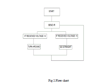
| The motors are triggered according to the voltage set in the program. If the received voltage is greater than the threshold value set in the program, then the motor is enabled and direct the robot accordingly in order to avoid the obstruction. If it is below the threshold value it is programmed in such a way that it goes straight. |
CONCLUSION |
| The obstruction detection robot performed as expected. We were able to implement all the functions specified in our proposal. We feel that this obstruction robot is very marketable because it is easy to use, comparatively inexpensive, low power consumption and highly reliable. This obstruction detection robot is therefore particularly used in applications such as remote controlled vehicles, unmanned vehicles, parking systems etc. |
| Applications of these types of robot are very wide. They are commonly used with defense systems. They are also used in toys. Their use can be extended to object tracking systems, used in foreign countries to track specified objects. |
ACKNOWLEDGEMENT |
| First of all, we extend our sincere thanks to Prof. Radhakrishnan K, Head of the department for providing us with the guidance and facilities for the mini project. We express our sincere gratitude to mini project coordinator Mr. Eldhose K A and staffs in charge, for their cooperation and guidance for preparing and presenting this mini project. We also extend our sincere thanks to all other faculty members of Electrical and Electronics Department and our friends for their support and encouragement. |
References |
|