ISSN ONLINE(2278-8875) PRINT (2320-3765)
ISSN ONLINE(2278-8875) PRINT (2320-3765)
Mashad Uddin Saleh1, Gazi Mahamud Hasan2, Mohammad Abdullah Al Shohel3, Md. Abul Hasnat Ferdous4, Biswajit Biswas Dipan5
|
| Related article at Pubmed, Scholar Google |
Visit for more related articles at International Journal of Advanced Research in Electrical, Electronics and Instrumentation Engineering
This paper describes the design of a 3-DOF robotic arm very much suitable for industrial purposes. The three DOF can perform lateral, vertical and grabbing movement profoundly. All of the three arm modules are driven by cables which are functionally equivalentto human muscles to perfectly imitate driving procedure of human arm. A highly adroit, light weight and largish workspace for industrial uses can make this robotic arm quite handful.
Keywords |
| Robotic arm, Control, Cylindrical coordinate, DOF, PWM |
INTRODUCTION |
| For over half a century robotics has been a staple of advanced manufacturing. As robots and their peripheral equipment become more sophisticated, reliable and miniaturized, these systems are increasingly being utilized for industrial, military and law enforcement purposes [1, 2]. The most common manufacturing robot for industrial purpose is the robotic arm [3, 4]. A robotic arm moves an end effector from place to place. A specific arm can be well equipped and designed with all types of end effectors which are fitted for particular application. Industrial robots are projected to do precisely the same thing, in a controlled environment, over and over again. If the arm is totally autonomous, then the robot puts in the exact sequence of movements in its memory, and does it again and again every time a new unit comes down the assembly line. Also, without any modification a robot works the way it is predefined. It can move to a fixed angle with a fixed velocity in a perfectly repeated way. |
| In this paper, we proposed a design of a light-weight and cost effective humanoid robotic arm to be used mainly in industry application like chemical and fertilizer industries, mechanical apparatus designers’ laboratory etc. The model proposed a 3-DOF design for this application. The arm is going to move an angle pre-set by the programmer, and reaching there it will move its shoulder portion downwards to capture the object by clinching its fist. After the capturing the arm is going to move again and put the object to desired place. According to this basic idea we proposed a model, designed it and controlled it with requisite program. Our proposed model can be used in ample ways to repudiate the risk in using hazardous materials, chemicals and sophisticated objects. |
CONTROL CIRCUIT AND OPERATION |
| While designing the arm, emphasise was given on the simplicity of the control circuit and design of the arm. The basic circuit connection diagram, principle of operation, and procedure are described below: |
A. Control Circuitry |
| The basic control circuitry consists of 3 pieces of DC motor, 2 pieces of Bidirectional Motor Driver / H Bridge (L 293), 1 piece of Atmel 8051 series 89S52 microcontroller, 1 piece of 3 Terminal Voltage regulators (7805) and 6 pieces of SPDT switches. For plausible results the control circuitry is first simulated in Proteus software. After successful simulation practical implementations are made. The whole simulation is performed and the software circuitry is imitated in the real life. |
| The basic connection to the motors for signal reception is shown below: |
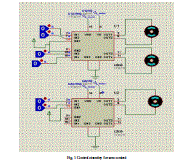 |
| Fig. 1 Control circuitry for arm control |
B. Operating Principle |
| In this project we have to deal with 3-D motion and we opted for cylindrical coordinates (r, θ, z) to accomplish the purpose. We kept the locus of the arm a circle with constant radius r. To take the target object to a different location and different height we used the movement along two coordinates (rotation along the circumference of the constant radius circle by the desired angle θ and subsequent upward or downward displacement along the z axis). To grab and release the target object we designed a gripper with a movable segment and two fixed segments that can hold the target object in either direction (according to the width of the target object). For moving along two coordinates (θ, z) and to change the grip-width we used a DC motor in each case and coupled it with simple pulley systems. The motor driver received the signals from the microcontroller and performed accordingly. For bidirectional rotation we have used H-bridge motor driver. |
| The step by step operation is given in the following block diagram: |
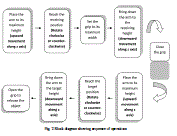 |
| Fig. 2 Block diagram showing sequence of operations |
| We have used real time object to show the viability of our model. The model is made up of wood and can carry a significant amount of load which makes it pretty reliable for industry application. The system capacity can be ameliorated by the insertion of stronger motors and some more preferable designs which can bolster more weight. |
C. Experimental Data |
| With our model, we performed some practical observations and got encouraging results. We used some light objects to fetch, carry and move one place to another. Those objects were different in weight and the time taken for their apparent motion was tabulated. The time taken was realistic and quite appropriate for real life industry applications. The data collected are given in a tabular form below: |
 |
| The figure of the proposed model and the model while in action are shown below. Fig. 3 shows the basic structure and Fig. 4 shows the model in real action (gripping the object and in a move). |
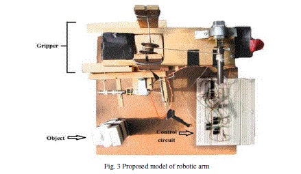 |
| Fig. 3 Proposed model of robotic arm |
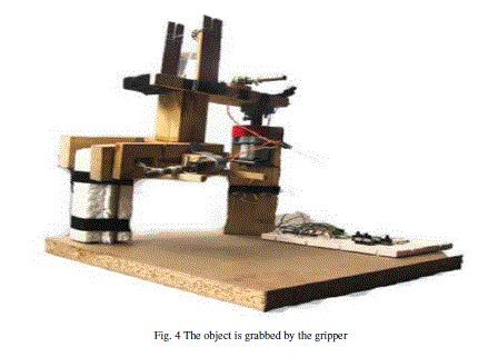 |
| Fig. 4 The object is grabbed by the gripper |
LIMITATIONS AND MODIFICATIONS |
| In our proposed model, motors are allowed to move in their rated speed and torque without any PWM therefore it is difficult to achieve better precision. Fully manual control through switching therefore proper timing of switching by operator is necessary for more realistic application. Some further modifications can be possible. Some are: |
| Using PWM with appropriate duty cycle can provide a better speed control of the motors [5]. |
| Automatic switching can be incorporated. In that case the current point, receiving point and target point is to be taken as input digitally and comparing these data the on-off switching sequence can be designed to make it more user-friendly. |
| The increased number of DOF will be effective for more flexibility. |
CONCLUSION |
| Due to some unavoidable constraints, the model lacks in several aspects. Nevertheless, it exhibits the basic working principle of simple low cost robotic arm. With some modifications it will certainly turn into a marketable concept. For more effective design two essential design analysis issues should be included, i.e., displacement analysis and tension analysis. A grasp systematic is also very useful for designing and manufacturing more convoluted robotic arms. |
ACKNOWLEDGEMENT |
| On a finishing note we express our gratitude to those all from BUET Machine Shop, Carpentry Shop and Sheet-metal shop who have assisted in our work. Without their sincere efforts, this model could not be brought to light. Finally we would like to take the opportunity to thank our course teachers for their valuable suggestions and guidelines. |
APPENDIX |
 |
 |
 |
References |
|