ISSN ONLINE(2278-8875) PRINT (2320-3765)
ISSN ONLINE(2278-8875) PRINT (2320-3765)
G.Maruthaipandian1, S.Ramkumar2, Dr.M.Muruganandam3
|
| Related article at Pubmed, Scholar Google |
Visit for more related articles at International Journal of Advanced Research in Electrical, Electronics and Instrumentation Engineering
In this paper proposes a simple but effective method of electric brake with energy regeneration for a brushless dc motor, of electric vehicle (EV). BLDC motor control utilizes the traditional proportional-integralderivative (PID) control and the distribution of braking force adopts fuzzy logic Conventionally, EVs use mechanical brake to increase the friction of wheel for the deceleration purpose. However, from the viewpoint of saving energy, the mechanical brake dissipates much energy since the EV’s kinetic energy is converted into the thermal one. In view of this, this paper discusses how to convert the kinetic energy into the electrical one that can be recharged to the battery. Thus, both the electric brake and energy regeneration are achieved. In comparison to other solutions, the new solution has better performance in regard to realization, robustness and efficiency. In this paper, we have chosen the three most important factors: SOC, speed and brake strength as the fuzzy control input variables. We have found that RBS can obtain appropriate brake current, which is used to produce brake torque. At the same time, we have adopted PID control to adjust the BLDC motor PWM duty to obtain the constant brake torque. PID control is faster than fuzzy control so the two methods combined together can realize the smooth transition since the braking kinetic energy is converted into the electrical energy and then returns to the battery, the energy regeneration could increase the driving range of an EV.
Keywords |
| Brushless dc (BLDC) motor, fuzzy control, Proportional-integral-Derivative (PID) Control, regenerative braking system (RBS). |
INTRODUCTION |
| Recently because environmental pollution and the energy crisis are rising globally, most industrialized countries have been attempting to reduce their dependence on oil as an electric cars, electric scooters, electric bicycles, electric wheelchairs, etc. Electric vehicles (EVs) are becoming important, not only as an environmental measure against global warming but also as an industrial policy [1-2]. In order for them to be used widely, the next-generation EVs must be safe and per-form well. The propulsion force generation mechanism which strongly influence the safety and running performance of the vehicle, the faster, more efficient, less noisy and more reliable Brushless dc motors (BLDCMs) have many advantages over brushed dc motors and induction motors, such as simple structure, high efficiency, high dynamic response, higher speed range, large starting torque, noiseless operation, etc. The regenerative braking does not operate all times, e.g., when the battery is fully charged, braking needs to be effected by dissipating the energy in a resistive load.[3-5] Therefore, the mechanical brake in the EV is still needed. EVs use mechanical brake to increase the friction of wheel for the deceleration purpose. However, from the viewpoint of saving energy, the mechanical brake dissipates much energy since the EV’s kinetic energy is converted into the thermal one. In view of this, this paper discusses how to convert the kinetic energy into the electrical one that can be recharged to the battery.[10-13] Thus, both the electric brake and energy regeneration are achieved A mechanical brake system is also very important for EVs’ safety and other operations |
| Coordination of EV mechanical braking and regenerative braking is achieved by a single foot pedal: The first part of the foot pedal controls the regenerative braking, and the second part controls the mechanical brake[6-8].This is a seamless transition from regenerative braking to mechanical braking. It cannot be simply achieved by traditional ICE vehicles |
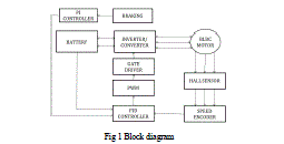 |
| Fig 1 Block diagram |
BRUSHLESS DC MOTOR DRIVES STRATEGIES |
| The BLDC motor is magnetic field generated by the stator and the magnetic field generated by the rotor rotation are the same frequency. Brushless dc (BLDC) motors are ideally suitable for EVs because of their high power densities, good speed-torque characteristics, high efficiency, wide speed ranges, and low maintenance. BLDC motor is a one of the type of synchronous motor. BLDC motors do not experience the “slip” which is normally seen in induction motors [16-18]. However, a BLDC motor requires relatively complex electronics for control. The BLDC motor, permanent magnets are mounted on the rotor, with the armature windings being fixed on the stator with a laminated steel core. Rotation is initiated and maintained by sequentially energy opposite pairs of pole windings that are said as form phases. Knowledge of rotor position is critical to sustaining the motion of the windings the rotor shaft position is sensed by a Hall Effect sensor, which provides signals to the respective switches. Whenever the rotor magnetic poles pass near the Hall sensors they give a high or low signal, indicating either N or S pole is passing near the sensors [22-26]. |
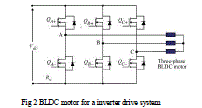 |
| The Hall Effect sensors are used to as the rotor position and from the Hall sensor outputs, it is determined the machine has reversed its direction. This is the ideal moment for energizing the stator phase so that the machine can start motoring in the counter clockwise direction in increase the motor performance.[19-20] |
MOTOR CONTROL AND MOSFET CONTROL OF REGENRATIVE |
A. Motor Control: |
| A control of permanent-magnet BLDC motor is PWM current control. It is based on the assumption of liner relationship between the phase current and the torque, similar to that in a brushed dc motor. Therefore, by adjusting phase current, the electromagnetic torque can be controlled to meet the requirement. The general structure of a current controller for a BLDC motor is instantaneous current in the motor is regulated in each phase by a hysteresis regulator, which maintains the current within adjustable limits. The rotor position information is sensed to enable commutation logic, which has six outputs to control the upper and lower phase leg power switches [9-10]. |
| The current reference is determined by a PI regulator, which maintains the rotor average speed constant. The drive for a BLDC motor lead is connected to high-side and low-side switches. The correlation between the sector and the switch states is noted by the drive circuit firing. At the same time, each phase winding will produce a back EMF; the back EMF of their respective windings [14-15]. A number of switching devices can be used in the inverter circuit, but MOSFET and IGBT devices are the most common in high-power applications due to their low output impedances |
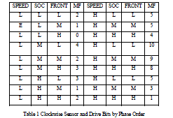 |
| Table 1 Clockwise Sensor and Drive Bits by Phase Order |
| If a BLDC motor, we must know the position of the rotor which determines the commutation. Hall Effect sensors are the most common sensor for predicting the rotor position. The BLDC voltage vector is divided into six sectors, which is just a one-to-one correspondence with the Hall signal six states. |
B. MOSFET control: |
| During deceleration period Regenerative braking can be achieved by the reversal of current in the motor-battery circuit, in merits of drives acting as a generator, return the current flow into the supply battery. With the low speed of the BLDC motor, winding back EMF cannot reach the voltage across the battery. The recovery of energy also cannot be achieved. Due to the presence of inductances in motor windings, these inductances of drive circuit can consists of the boost circuit. In order to achieve the recovery of energy, we have to increase the voltage on the dc bus through the inductor accumulator. We turn off all MOSFET on the high arms of H-bridge and control the low arms of H-bridge with PWM. Armature current of the BLDC motor and in which there is only one power switch is operated within each commutation state on bidirectional dc/ac converter switching signals. According to the principle of the volt-second balance and one can conclude that change in the equivalent inductor voltage is zero over one electric circuit. |
| The conventional start-up method reveals some unexpected drawbacks that might degrade the performance of the BLDC motor. To overcome these restrictions, a simple start-up method not only to achieve the maximum starting motor torque but also to control the stator current is proposed more over apart from speed control the torque ripple is responsible for speed oscillations. The torque pulsations in PMBLDC motors are generally resulted from the deviation from ideal conditions. Regeneration starts only when the brake pedal is pressed. Once the brake pedal is depressed, in accordance with the position of the brake pedal, a corresponding proportion of brake torque is applied. Then, the brake torque due to the regenerative brake control strategy is divided into regenerative braking and friction braking. |
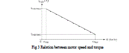
| K value increase from 0 to 1.the dynamic energy of the electric vehicle will be transferred into braking torque and the heat instead of being recovered into the battery in the actual application of the energy regeneration, the relation between the motor speed and braking torque. In considered the riding feeling and safeness, he is hoping that the EV can provide a smooth and reliable brake system. Therefore, the proposed method regulates the braking torque to the motor speed, rather than as a constant braking torque of the system. |
| If the driver wishes to accelerate the vehicle, he depresses the accelerator. Depending on the amount of depression of the accelerator pedal, a corresponding driver torque request is sent to the vehicle through various power train systems such as battery and motor models. The MOSFET can be used in high power application. In turn off time and leakage current also less in compared into IGBT devices. |
 |
ELECTRIC VEHICLE |
| Electric vehicle become the most promising alternative to the ICE vehicle in the EVs have use a battery system which can be recharged from standard power outlets then EVs performance characteristics comparable to, in not better than of ICE vehicles. The electric vehicles can be used an regenerative braking as a process of recycling the brake energy. |
A. Electric Vehicle Modelling: |
| The electric vehicle has been used as MATLAB/SIMULINK on modelling circuits. the various power train system component using the driver block and torque propagates to the system and realizes vehicle motion. System-level simulators have been modelled by using empirical data that are based on measurements supplied by component manufacturers or extended from measurements obtained from literature sources. Other component models are physical or analytical in nature and are modelled by mathematical equations the electric vehicle model weighs about the 1326 kg inclusive of battery. The vehicle has a frontal area of the 2.578m2, with a drag coefficient of 0.3 and rolling resistance of 0.00267 Ω. The values assigned are based on a rough estimate of a mid-sized car. The electric motor chosen is a BLDC motor with a peak power of 40 kW. The battery pack is a Li-Ion battery. It has a nominal voltage of 72 V, with energy content of 1.2 kWh and weight around 20 kg the various |
B. Electric Machine: |
| The electric machine can be using the power from the battery The electric machine works as a motor to propel the electric vehicle when positive power is fed in and as a generator when negative power is fed in the electric vehicle. EM is modelled as a look-up table with motor-generator characteristics (efficiency curve) of a BLDC motor MC_PM8 of 8 kW from ADVISOR. This electric motor downsized to that of 8 kW to meet the specifications provided on the circuit. Downsizing is done by reducing the torque with a scale factor determined by the ratio of the default power (8 kW) and the required power (7 kW). |
C. Regenerative Braking Sub system: |
| According to the distribution of regulation of brake force on front and rear wheels, in the time front and rear wheels braking force can be calculated. the fuzzy logic controller can be obtain the value of regenerative braking force then the front wheels from mechanical force and rear wheels from on regenerative braking force. The pedal sensor can be obtain the driver required the braking force. |
(i) Distribution of Braking Force: |
| The regenerative braking of electric vehicle, mainly the braking force is front wheel braking force and rear wheel braking force .in two parts of front wheel braking force are front wheel frictional braking force and regenerative braking force. The front and the rear wheel braking force allocation strategy in the electric vehicles is z<0.1, the total braking is all borne by the drive and same times front wheel not involved in the braking of electric vehicle. Then 0.1 < z < 0.7 the braking force can be allocated by the electromechanical composite brake. |
(ii) Fuzzy Control: |
| The electric vehicle of regenerative braking force consists of many factors are constantly changing, recycling the energy. The fuzzy logic controller of regenerative braking has different factors in fuzzy control theory can be applied the braking force and three inputs are front wheel barking force, speed and SOC. |
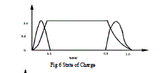
| Front braking force can be driver braking requirement are concerned with the driving safety. The SOC is the battery less than 10% and same time resistance is high. The battery can be charging the large current the ratio RBS should be increase and SOC can be greater than 90%.the se6 the SOC to be low, middle, and high. |
| The speed of electric vehicles can important role of driving safety. Then speed is high also increased the ratio of regenerative braking. |
 |
| The fuzzy control in braking force is low, middle, and high. Then SOC is low middle and high. Then speed is also low, middle, and high. |
 |
 |
(3) Proportional Integral Derivative (PID) Control: |
| The PID control used as constant brake torque and different braking force values will give different PWM in order to maintain the brake constantly. A constant electrical braking torque can be achieved during the fuzzy inference. The braking torque real time controlled by PID control. |
D. Battery Sub System: |
| The brake control strategy system can be reaches the battery subsystem. In the subsystem positive power discharged the battery system and negative power charges on the battery .the performance of the battery can be set the initial value of SOC in 90%. The discharge block depends on the state of charge level. Then from demand power and maximum voltage enabled the SOC, then calculate the current and supply it to the motor. Then maximum amount of current can be handled in motor. This current is again limited and maximum current capability of the generator. No current is withdrawn or put back during this phase. The lithium ion battery can be used the battery system. |
E. Vehicle Subsystem |
| The electromechanical torque produced by the motor is fed into the vehicle subsystem to propel the vehicle. This model has a central body subsystem and four tire subsystem. The delft tyre model helped in keeping a watch on the variation of slip, at no point during the simulation, wheel lock can occur .a wheel lock is would prevent regeneration and destabilize the vehicle. |
SIMULATION RESULTS |
| Under the environment of MATLAB and Simulink, the RBS is modelled, and the drive cycle is performed. The test is per-formed according to urban driving schedules. |
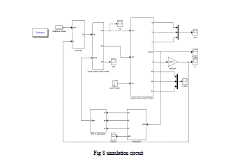 |
| Fig 8 simulation circuit |
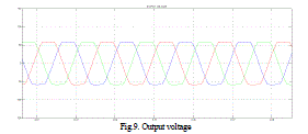
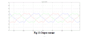
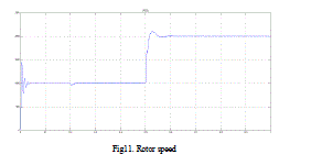
| A prototype of BLDC motor has been built to validate the theoretical results as well as the simulation by using FUZZY Controller. Fig 5 shows simulation diagram of BLDC motor with FUZZY controller. Fig 6 shows the rotor angle and EMT and Fig 8 show the BackEMF waveform for BLDC drive. |
 |
 |
 |
CONCLUSION |
| A new speed control strategy for a PMBLDC using the back emf as a commutation signal has been simulated. A new torque control scheme of BLDC has been found as a promising vibration and noise. Moreover, it may also be used in the fans with PMBLDC motor drives on the trains. By implementing the proposed control strategy the torque ripple and speed oscillation can be recovered and can make motor run more efficient for long duration of life time. |
References |
|