Power electronics plays an important role in controlling the drives. Digital control technology has been rapidly developed for power electronics and electrical drives, and it has been the impetus to the widespread use of a permanent magnet synchronous motor in many industrial applications such as chip mount machines, semiconductor production machines, high-resolution computerized numerically controlled machine tools, robotics, and hard disk drives. A PMSM has low noise, low inertia, high torque-tocurrent ratio, high efficiency, robustness, and low maintenance cost. We propose a genetic algorithm (GA) based speed regulator system for a permanentmagnet synchronous motor. By using the GA the motor acceleration observer as well as a speed regulator is designed. In terms of linear matrix inequalities, sufficient conditions for the existence of the regulator and observer are derived. Simulation and experimental results are given to verify that the proposed digital control method can be successfully used for a PMSM under model parameter and load torque variations.
Keywords |
| Genetic algorithm, speed regulation,
Permanent magnet synchronous motor, driver, space
vector modulation. |
INTRODUCTION |
| The development and availability of very highenergy
density Permanent Magnet materials has
contributed to an increased use of the permanent magnet
synchronous motor (PMSM) in high performance
applications. High-speed electric machines are of interest
as direct drives for high-speed milling machines,
compressors and pumps, yielding a high output power at
rather small machine dimensions. The high-speed
permanent magnet Synchronous motor with sinusoidal currents is the best choice for high-speed operation
because of the high efficiency, low torque ripple, low
noise and excellent control performance. The PMSM
eliminates rotational cogging torque due to permanent
magnet preferred positions, decreases core loss and thus
increases efficiency, provides excellent torque to volume
and power-to volume ratios and has a linear current versus
torque relation. In the PMSM, in order to generate smooth
torque and thus reduce noise and vibration, the current
waveform should match the shape of the motor
electromotive force (emf). The GA has found many
applications in the area of the automatic tuning process
for conventional and intelligent controllers. Some
research has been conducted using genetic algorithms to
help online or off line control systems. It has primarily
been utilized as an off-line technique for performing a
directed search for the optimal solution to a problem. In
this paper, the GA is used on-line in real-time controller
implementation to adaptively search through a population
of controllers and determine the member most fit to be
implemented over a given sampling period. |
II.PERMANENT MAGNET SYNCHRONOUS MOTOR |
| The development of high-quality permanent
magnet materials into commercial production has
encouraged several manufacturers to launch various
Permanent Magnet Synchronous Machines (PMSM) into
the market. Permanent Magnet Synchronous Machines
have been applied to servo drives for a long time already
and nowadays, there are quite large permanent magnet
synchronous machines also in industrial use. In wind mill
generators |
A. Equivalent circuit of PMSM |
| Similarly as separately excited synchronous
machines, the PM Synchronous Machines are usually treated in a dq reference frame fixed to the rotor, Figure
2.7. The equivalent circuit of the machine is almost the
same as for a separately excited synchronous machine. |
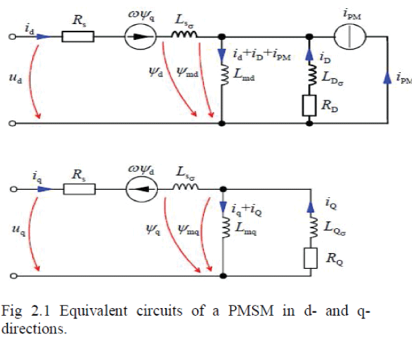 |
| The permanent magnet can be depicted by a
current source iPM in the rotor circuit; in the magnetizing
inductance, this current source produces the permanent
magnet’s share of the air gap flux linkage ��PM = iPM Lmd.
If also the damper windings are included in the model, the
voltage equations of a PM machine differ from a
separately excited synchronous machine only by the fact
that the equation for the field winding is lacking. Current
vector control is quite widely adopted to the control of
permanent magnet synchronous machines. A good
performance can be achieved by this control method
particularly because the parameters of PM machines do
not vary as much depending on the operating situation as
the parameters of other machine types do. Particularly in
the motors applying surface mounted magnet rotor
structures, the inductances remain constant quite well, and
therefore the effect of armature reaction is small. Thus,
the voltage equations of the PM machine are given in the
rotor reference frame in the familiar form The flux
linkage components in the equations are determined by
the equations |
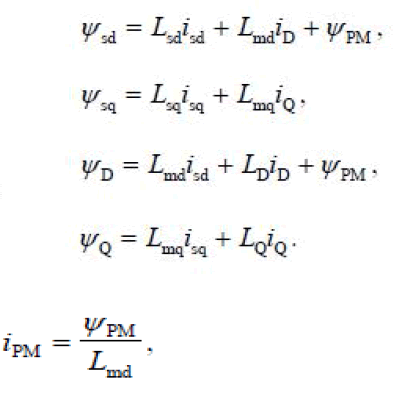 |
| Now the definitions for the flux linkages do not
deviate from the definitions of a separately excited
synchronous machine. However, it is worth noticing that
due to the saturation of the magnetizing inductance Lmd,
iPM is not constant. |
III.DRIVER |
| In electronics, a driver is an electrical circuit or
other electronic component used to control another circuit
or other component, such as a high-power transistor. They
are usually used to regulate current flowing through a
circuit or used to control the other factors such as other
components, some devices in the circuit. The term is often
used, for example, for a specialized integrated circuit that
controls high-power switches in switched-mode power
converters. An amplifier can also be considered a driver
for loudspeakers, or a constant voltage circuit that keeps
an attached component operating within a broad range of
input voltages. Typically the driver stage(s) of a circuit
requires different characteristics to other circuit stages.
For example in a transistor power amplifier, typically the
driver circuit requires current gain, often the ability to
discharge the following transistor bases rapidly, and low
output impedance to avoid or minimize distortion. Every
device, whether it is a printer, disk drive, or keyboard,
must have a driver program. |
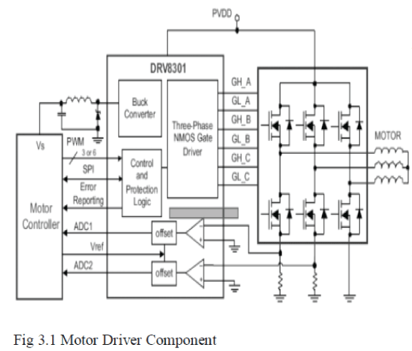 |
| The Motor Driver is the Integrated Part with
Motor Power and Control Components. The Driver
Controls the Motor Drive according to the input command
from Motor Controller and power Circuit. In figure 4.5
DRV8301 is an example of motor Drive Components. |
IV.SPACE VECTOR PWM (SVPWM) |
| Space Vector Modulation (SVM) can directly
transform the stator voltage vectors from an α, β-
coordinate system to Pulse Width Modulation (PWM)
signals (duty cycle values).The standard technique for
output voltage generation uses an inverse Clarke
transformation to obtain 3-phase values. Using the phase
voltage values, the duty cycles needed to control the
power stage switches are then calculated. Although this
technique gives good results, space vector modulation is
more straightforward and realized more easily by a digital
signal controller. SVPWM is actually just a modulation
algorithm which translates phase voltage (phase to
neutral) references, coming from the controller, into
modulation times/duty-cycles to be applied to the PWM
peripheral. SVPWM can directly transform the stator
voltage vectors from the two-phase α,β-coordinate system
into pulse-width modulation (PWM) signals (duty cycle
values). Proverbial motor formulae are: |
 |
| U1 is stator voltage vector, ��1 is flux vector, and i1 is
stator current vector. |
| When U1 is a standard sine wave, that is the same size and
direction continuous change, the trajectory is an ideal
circle. So, |
 |
| When R1 *i1<<U1: |
 |
| Flux trajectory depends on voltage vector.
So we can design the circuit of DC to 3-phase AC |
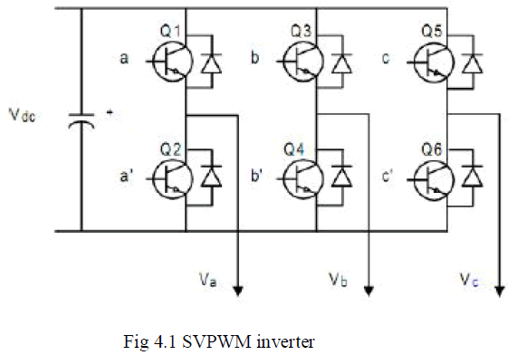 |
| As shown in figure 4.1, in the circuit diagram, have 6
power switch a, b, c, a’, b’, c’ plot out they into 2 groups,
S [a, b, c], S’ [ a’, b’, c’], they control the switch
ON/OFF, and they mutex, |
 |
| Its means each voltage vector is coded by the three-digit
number and have eight possible switching states (vectors)
are feasible. |
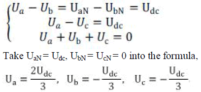
| For example: SX = [1, 0, 0] |
| The point [a], [b’], [c’] switch ON, an [a’], [b’], [c] switch
OFF. |
| UaN = Udc, UbN = UcN = 0 |
| In motor theory, |
 |
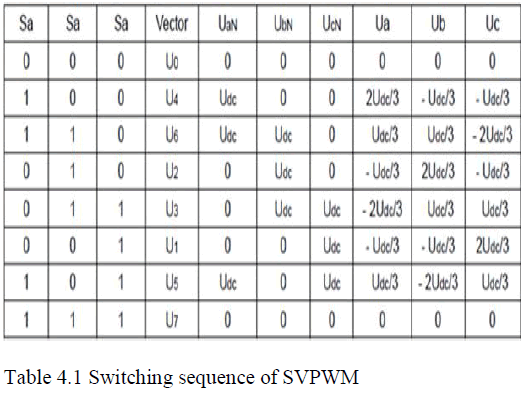
| Similarly, can calculate other switching states, below in
Table 4.1 |
 |
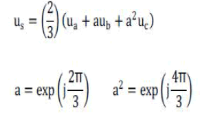
| Form formula (4.3) and (4.4), the voltage space vector
formula: |
 |
| Take table 4.1 vectors: |
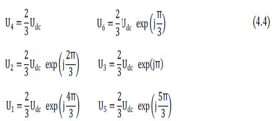 |
| All of non-zero vectors have the same amplitude 2 Udc /3,
and between border two vectors angle is , π/3=60° for
example, f=50Hz, the vector change |
 |
| Graphical representation of all combinations of the
hexagon shown in figure 4.3. There are six non-zero
vectors, U0, U60, U120, U180, U240, U300, and two zero
vectors, O000 and O111, defined in α, β coordinates. |
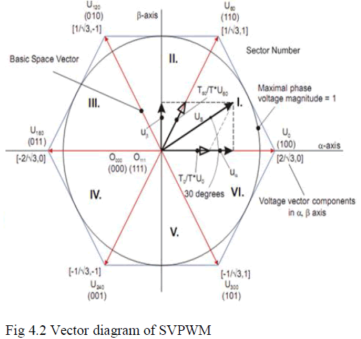 |
| In figure 4.3, the red line plot out the hexagon into six
sectors, every between border two vectors angle is 60°,
the border two vectors and zero vector could compose
random voltage vector. |
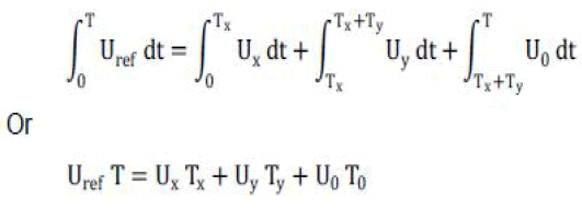 |
| This formula means, in sector the voltage
vector rotating course could plot out many small part,
it’s have the same effect. So, in the interest of bring 3-
phase sine AC voltage, use the voltage vector compose,
begin from U4(100), every time increase a little
increment, every increment could compose from
between border two vectors and zero vector. Then the
enactment voltage vector equivalent with the rotating
voltage vector, and that all is SVPWM. |
V.GENETIC ALGORITHM |
| A. Introduction |
| Genetic Algorithms (GAs) are the main paradigm of
evolutionary computing. GAs is inspired by Darwin's
theory about evolution–the "survival of the fittest". In
nature, competition among individuals for scanty
resources results in the fittest individuals dominating
over the weaker ones. |
| a. GAs are the ways of solving problems by
mimicking processes nature uses; ie., Selection,
Crossover, Mutation and Accepting, to evolve a
solution to a problem. |
| b. GAs is adaptive heuristic search based on the
evolutionary ideas of natural selection and
genetics. |
| c. GAs is intelligent exploitation of random search
used in optimization problems. |
| d. GAs, although randomized, exploit historical
information to direct the search into the region
of better performance within the search space. |
| e. The biological background (basic genetics), the
scheme of evolutionary processes |
| B. The Genetic Algorithm for the PMSM |
| During time step, each member of the population
is evaluated on how well it minimizes the ITAE. For each
member of the population, the GA computes the speed |
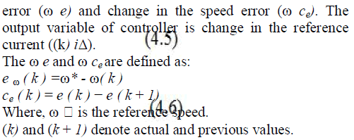 |
| In this application, feedback signals are the position θ and
the phase currents a, b, c, d i and the position signal is
used to calculate the speed. The switching signal
generator is used to control turn-on angle θ on, turn-off
angle θ off, and pulse width modulation duty cycle. |
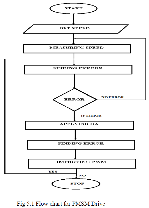
| The steps for speed regulation are summarized as follows: |
| a) Sample the speed signal of the PMSM. |
| b) Calculate the speed error and change in speed
error. |
| c) Choose the number of digits to represent each
controller parameter Kp and Ki. Choose
crossover probability (pc) and mutation
probability (pm). |
| d) Generate an initial population of Kp and Ki gains
(we make a random selection) Initialize sample
time T and set time t. |
| e) Generate Δi(k), for each population member Ci,
i=1,2,...n using the conventional PI control laws.(
i( k ) K .e ( k ) K .e ( k ).T p ω i ω Δ = + ) |
| f) Assign fitness to each element of the population
Ci, i=1, 2, 3, n, P E (k) 1 ω = 8 |
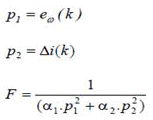 |
| g) Produce the next generation using GA operators
and let t: = t+T go to step (d) |
| h) The maximally fit Ci becomes C* and send the
change of control action (i*(k)) to control the
drive. Where i* ( k ) is the inferred change of
reference current by the controller. At the kth
sampling time and defined as i* ( k ) = i* ( k +
1)+Δi( k ) (11) |
| Where, i* (k + 1) is the previous reference
current. |
 |
VI.SIMULATION OVERVIEW |
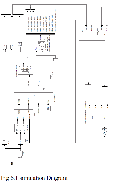
| A. Simulation of proposed system |
 |
 |
 |
 |
VII.CONCLUSION AND FUTURE WORK |
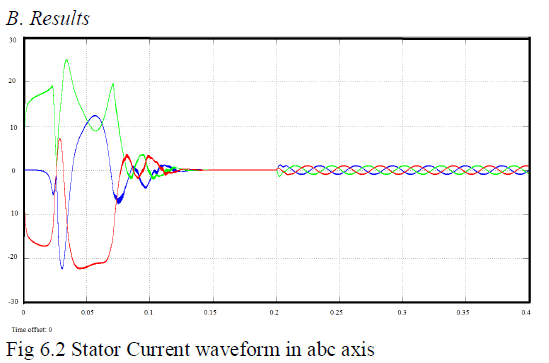
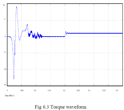
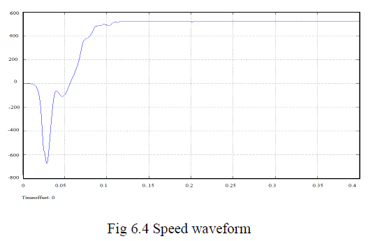
| In this paper, a Genetic algorithm based PI speed
controller for PMSM drive system is presented.
Mathematical model of a PMSM fed by three phase
inverter is realized, Genetic PI speed controller for speed
regulation of PMSM are designed. The Genetic PI and
conventional PI controller are designed and simulated
individually and results are given. From the simulation
results, it is clear that the designed the Genetic PI
controller has better speed response than conventional PI
controller. In Future, I will implement this in hardware. |
References |
- Barkat. S, Tlemcani. A, and Nouri. H, “Non interactingadaptive control of PMSM using interval type-2 fuzzy logicsystems,” IEEE Trans. Fuzzy Syst., vol. 19, no. 5, pp. 925–936, Oct. 2011.
- Buccella.C, Cecati.C, and Latafat. H, “Digital control ofpower converters—A survey,” IEEE Trans. Ind. Informat.,vol. 8, no. 3, pp. 437– 447, Aug. 2012.
- Choi. H. H, N. Vu. T.-T, and Jung. J.-W, “Digitalimplementation of an adaptive speed regulator for a PMSM,”IEEE Trans. Power Electron., vol. 26, no. 1, pp. 3–8, Jan.2011.
- Corradini. M. L, Ippoliti. G, Longhi. S, and Orlando. G, “Aquasi sliding mode approach for robust control and speedestimation of PMsynchronous motors,” IEEE Trans. Ind.Electron., vol. 59, no. 2, pp. 1096– 1104, Feb. 2012.
- Leu. V. Q, Choi. H. H, and Jung. J.-W, “Fuzzy sliding modespeed controller for PM synchronous motors with a loadtorque observer,” IEEE Trans. Power Electron., vol. 27, no.3, pp. 1530–1539, Mar. 2012.
- Lin. C.-K, Liu. T.-H, and Yang. S.-H, “Nonlinear positioncontroller design with input–output linearisation techniquefor an interior permanent magnet synchronous motor controlsystem,” IET Power Electron., vol. 1, no. 1, pp. 14–26, Mar.2008.
- Liu .H and Li. S, “Speed control for PMSM servo systemusing predictive functional control and extended stateobserver,” IEEE Trans. Ind. Electron., vol. 59, no. 2, pp.1171–1183, Feb. 2012.
- Nagoorkani.A, “Control Systems”, RBA Publications, FirstEdition, 1998.
- NgaThi-Thuy Vu, Dong-Young Yu, Han Ho Choi, “T–SFuzzy-Model-Based Sliding-Mode Control for Surface-Mounted Permanent-Magnet Synchronous MotorsConsidering Uncertainties” IEEE transactions on industrialelectronics, vol. 60, no. 10, oct 2013.
- Rashid M.H., “Power Electronics Circuits, Devices andApplications ", Prentice Hall India, Third Edition, NewDelhi, 2004.
- Ronald S. Rebeiro and M. NasirUddi “Performance Analysisof an FLC-Based Online Adaptation of Both Hysteresis andPI Controllers for IPMSM Drive,” IEEE transactions onindustry applications, vol. 48, no. 1, jan/feb 2012.
- Sen. P. C, Principles of Electric Machines and PowerElectronics, 2nd ed. New York, NY, USA: Wiley.
- Takeo Ishikawa, Yutaro Seki, and Nobuyuki Kurita,“Analysis for Fault Detection of Vector-ControlledPermanent Magnet Synchronous Motor with PermanentMagnet Defect” IEEE transactions on magnetics, vol. 49, no.5, may 2013.
- Xia. Y, Yang. P and Fu. M, “Constrained infinite-horizonmodel predictive control for fuzzy discrete-time systems,”IEEE Trans. Fuzzy Syst., vol. 18, no. 2, pp. 429–436, Apr.2010.
- Urresty. J, Riba. R. J, and Romeral. L, “A back-emf basedmethod to detect magnet failures in PMSMs,” IEEE Trans.Magn., vol. 49, no. 1, pt. 3, Jan. 2013.
|