ISSN ONLINE(2278-8875) PRINT (2320-3765)
ISSN ONLINE(2278-8875) PRINT (2320-3765)
Prof. Lalit Kumar Wadhwa1, Hemangi Vinchurkar2, Mugdha V. Patil2
|
| Related article at Pubmed, Scholar Google |
Visit for more related articles at International Journal of Advanced Research in Electrical, Electronics and Instrumentation Engineering
This paper further improves the previous work made to reduce the leakage power of electric home appliances. All the electric appliances consume electricity when they are in standby mode. It is one of operating mode of an appliance in which the appliances are not performing their primary task. In this paper a zero leakage power saving system is introduced which will saves the power when only leakage power is associated with the appliances. The appliances will be physically disconnected from mains supply whenever device remains in standby mode for some specific time. The system has three modes of operations – compulsory ON mode, compulsory OFF mode and Intelligent mode. In compulsory ON mode all the appliances will perfume their primary function, in compulsory OFF mode all the appliances will be detached from the mains supply and in intelligent mode the PIR sensors senses the motion and accordingly the electrical appliances will be turned on or off as per requirement. In this way the intelligent mode will saves the energy by making the standby power equal to zero and if the standby power get reduced then the total power consumption also get reduced and it reduces our electricity bill too.
Keywords |
| Standby Power, electrical appliances, compulsory ON, compulsory OFF, intelligent mode, PIR sensor. |
INTRODUCTION |
| In recent years global warming and energy conservation becomes an attention seeking issue due to the human activity such as the burning of fossil fuels. This issue is now recognized by everyone and the major part of this issue is due to carbon dioxide, produced by burning fossil fuels such as petroleum, coal and natural gases etc. Moreover, global warming is now noticed by everyone because of climate changes, the widespread melting of ice and rising sea levels. Therefore, strong remedial action should be taken as soon as possible. The fossil fuels are the most common conventional source of energy used in residential facilities and this power consumption makes up the larger part of the consumption in the world. Higher efficiency, lower power consumption in household appliances and industrial equipments that use electricity generated from burning carbon-containing fuels are all a necessity. There is around 10 - 12% of total household power being consumed during a standby mode. Therefore many researchers have been done to reduce this standby power consumption in appliances and equipment. The average household power consumption dedicates 11% of its energy budget to lighting [1]. The power consumption of lamps in a home is a factor which cannot be ignored. To save lighting energy, the pyro electric infrared (PIR) luminaire is now in wide use. Because the PIR luminaire turn on when the PIR sensor is activated and therefore no energy is wasted. The luminaire with its built-in PIR sensor not only turns off the electricity when no user is near the PIR sensor but also turns it on instantly when someone enters the room and off again after the individual exits. This luminaire is used widely not only for automatic room light detection [2] and home surveillance [3] but also in smart homes [4]-[5]. The luminaire helps us to avoid wastage of energy even if we leave the lights on for hours on end, which is great for energy saving, security and safety. |
| A literature review for this paper has been conducted in order to discuss the most recent published information in relevance with standby consumption. The focus of this review is to summarize the methods and results of other author’s reports and compare with the results of this study. The form of the literature review is thematic with the topics as are presented in bulletin points below: |
| Standby consumption estimates per household: There have been various National studies conducted worldwide to estimate standby power losses in households. Standby power use, the average standby consumption as a fraction of total electricity use and the number of appliances and households measured, will be reviewed. |
| Ownership and Penetration rate. |
| Relationship between standby consumption and household characteristics: Household characteristics that may affect the standby consumption of households such as income, age of participants and level of education will be showed. Consumer awareness and behavioral changes will be also reviewed. Standby power is a new phenomenon. Two decades ago, consumers could simply switch off their devices, assured that their electricity meter would stop. However, nowadays, meters in most houses continue to run and standby consumption is the cause. |
| There are three states of the PIR luminaire, 1. Cut-off state 2. Standby state 3. Lightning state. In the cutoff state the luminaire is unplugged from its energy source and does not consume any electricity. In the standby state the luminaire is connected to a power supply, but if no user is approaching it does not turn on the light. In the lighting state the PIR sensor is activated, and as a result of reduced light intensity and temperature the PIR will turn on the appropriate devices. Though the luminaire in the standby state is not performing its main function but it is often performing some secondary functions like sensing IR, daylight and temperature. In such a situation the PIR cannot be turned off unless the unit is detached from the mains power supply. This power is compulsory and this power consumption by the PIR is called “standby power”. The internal functions require not only a specific low dc voltage but also continuous power supply by an ac/dc converter which has no power-off switch. The converter, which acts as a power supply in the luminaire, converts this AC to low DC voltage for the internal functions operations. The PIR consumes about 1 to 3 watt but it is much more times than the power actually used for the internal functions. If the standby power of a PIR draws the power for 24 hours then its sum becomes significant. Since in 2000 as the International Energy Agency (IEA) adopted a proposal to reduce the standby power of all electrical apparatus to less than 1 Watt within ten years [6], the reduction of the standby power of the PIR luminaire has remained an important issue. |
| In this paper a new kind of PIR luminaire is proposed whose standby power consumption is reduced up to 1mW and this design is called a “zero standby power using PIR luminaire”. |
II.SYSTEM MODEL AND ASSUMPTIONS |
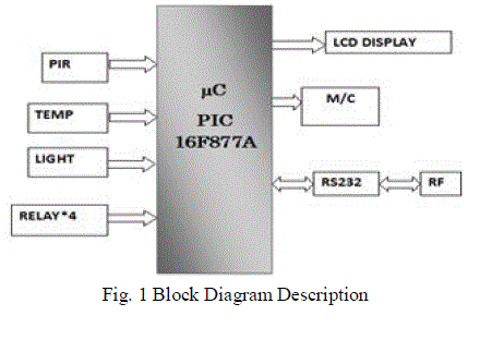
| As discussed in the introduction, the PIR luminaire is turned on only when any motion is detected. The luminaire has a photo resistor to detect light and also there is temperature sensor to detect the temperature. If there is enough light, the lighting does not turn on even if any motion is detected, while otherwise it will immediately turn on when motion is detected. Similarly the fan or air conditioner will turned on or off. The lighting duration, sensitivity adjustment and the threshold of PIR all are its internal functions. |
 |
| 1. Power supply |
| The basic step in the designing of any system is to design the power supply required for that system. The steps involved in the designing of the power supply are as follows: |
| Determine the total current that the system sinks & the voltage rating required for the different components. The bridge rectifier and capacitor input filter produce an unregulated DC voltage which is applied at the input of 7805.As the minimum dropout voltage is 2v for IC 7805, the voltage applied at the input terminal should be at least 7 volts. C1 (1000 μf / 65v) is the filter capacitor and C2 and C3 (0.1 pf) is to be connected across the regulator to improve the transient response of the regulator. Assuming the drop out voltage to be 2 volts, the minimum DV voltage across the capacitor C1 should be equal to 7volts. |
| Power supply design: |
| The average voltage at the output of a bridge rectifier capacitor filter combination is given by |
| Vin(DC) = Vm – Idc / 4 f C1 |
| Where, Vm=√2 Vs and Vs = rms secondary voltage |
| Assuming Idc to be equal to max. load current, say 100mA |
| C = 1000 uf / 65v , f=50hHz |
| 15 = Vm – 0.1 / 4*50*1000*10¯6 |
| 15= Vm – 0.1 / 0.2 |
| Vm=15.5 volts |
| Hence the RMS secondary Voltage |
| Vrms = Vm / √2 |
| = 15.5 / √2 |
| =15.5 / 1.41421 |
| =10.9601 volts |
| So we can select a 15v secondary Voltage |
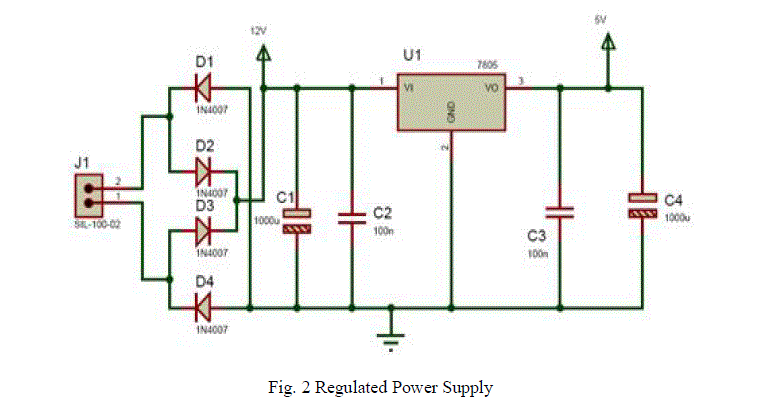 |
| In this system most of the components require 5 V as operating voltage such as micro controller, MAX 232, LCD etc. The total current, which our circuit sinks from the power supply, is not more than 100 mA. Here the Regulator IC 7805 is used that gives output voltage of 5V.The minimum input voltage required for the 7805 is near about 7 v. Therefore the transformer with the voltage rating 230v-10v and current rating 500/750 mA are used. The output of the transformer is 12 V. This voltage is converted into 12 V DC by Bridge rectifier circuit. |
| The reasons for choosing the bridge rectifier are, the TUF is increased to 0.812 as compared the full wave rectifier. The PIV across each diode is the peak voltage across the load = Vm, not 2Vm as in the two diode rectifier output of the bridge rectifier is not pure DC and contains some AC some AC ripples in it. To remove these ripples capacitive filter are used, which smoothens the rippled output which is applied to 7805 regulators IC that gives 5V DC. The capacitor filters are used here since it is cost effective, readily available and not too bulky. |
| 2. PIC Microcontroller and PIR |
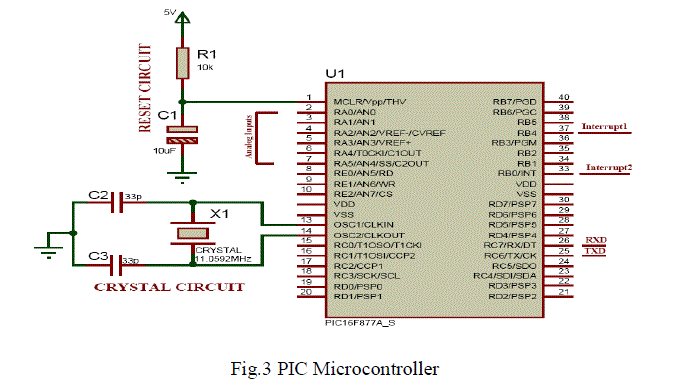
| The microcontroller receives the signals according to the operating mode of the system. If the system is in compulsory ON mode then all the appliances will remain ON and they are connected to the ac power supply and all the devices are performing their primary function. If the system is operated in compulsory OFF mode, all the appliances will detach from mains ac supply. In intelligent mode PIR will senses the motion and according to the requirement it sends signal to the PIC microcontroller |
 |
| 3. Reset Circuit: |
| Reset is used for putting the microcontroller into a 'known' condition. That practically means that microcontroller can behave rather inaccurately under certain undesirable conditions. In order to continue its proper functioning it has to be reset, meaning all registers would be placed in a starting position. Reset is not only used when microcontroller doesn't behave the way we want it to, but can also be used when trying out a device as an interrupt in program execution, or to get a microcontroller ready when loading a program. |
| In order to prevent from bringing a logical zero to MCLR pin accidentally, MCLR has to be connected via resistor to the positive supply pole and a capacitor from MCLR to the ground. Resistor should be between 5 and 10K and the capacitor can be in between 1μf tp 10 μf. This kind of resistor capacitor combination, gives the RC time delay for the μc to reset properly. |
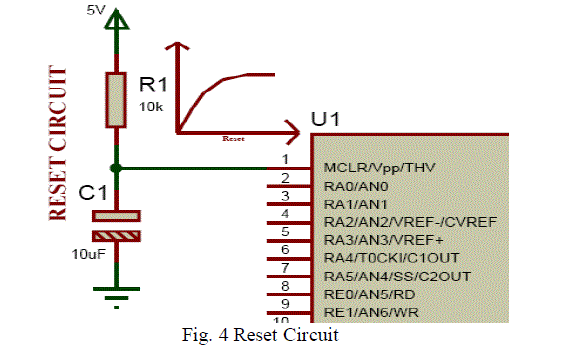 |
| As shown in the above circuit we are connecting an RC circuit to the MCLR (pin1) of μC .The PIC μC has an active low reset, therefore we connect an RC circuit. As shown the capacitor is initially at 0v.It charges via the supply through a 10 Kilo ohm resistance in series, therefore the reset time of our circuit is: R*C = 10kohm * 10 μf = 100 msec |
| Recommended time of reset = 1msec, Here the RC time can vary from 10 msec to 100 msec. |
| 4. Crystal Circuit: |
| Pins OSC1 & OSC2 are provided for connecting a resonant network to form oscillator. Typically a quartz crystal and capacitors are employed. The crystal frequency is the basic internal clock frequency of the microcontroller. |
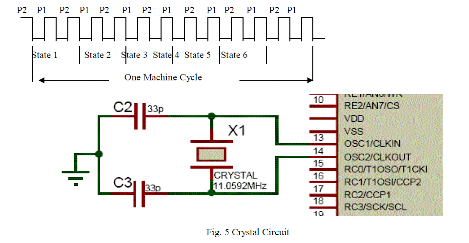 |
| Here two ceramic capacitors which are basically used for filtering. That is to give a pure square wave to the μC. The basic rule for placing the crystal on the board is in such a way that it should be as close to the μC as possible to avoid any interference in the clock. Baud Rate Formula |
 |
| 5. Liquid Crystal Display: |
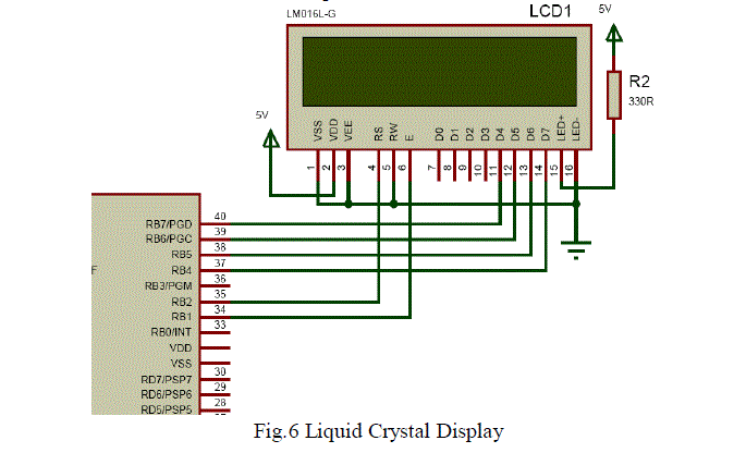
| LCD has 2 Power Sources 1. VCC and GND is at 1 and 2 no. pins of LCD which are used to drive the LCD 3mA current consumption and 2. VCC and GND is at 15 and 16 no. pins of LCD used to drive the backlight of LCD 100 mA current. Total current consumption = 3mA + 100mA = 103 mA So in order to reduce the current requirement, connecting a 330 ohm resistance in series with the backlight pin VCC, this reduces the current consumption (100mA / 330ohm =0.303 mA). Therefore new total current consumption is 0.303mA+3 mA =3.303 mA. |
 |
III IMPLEMENTATION |
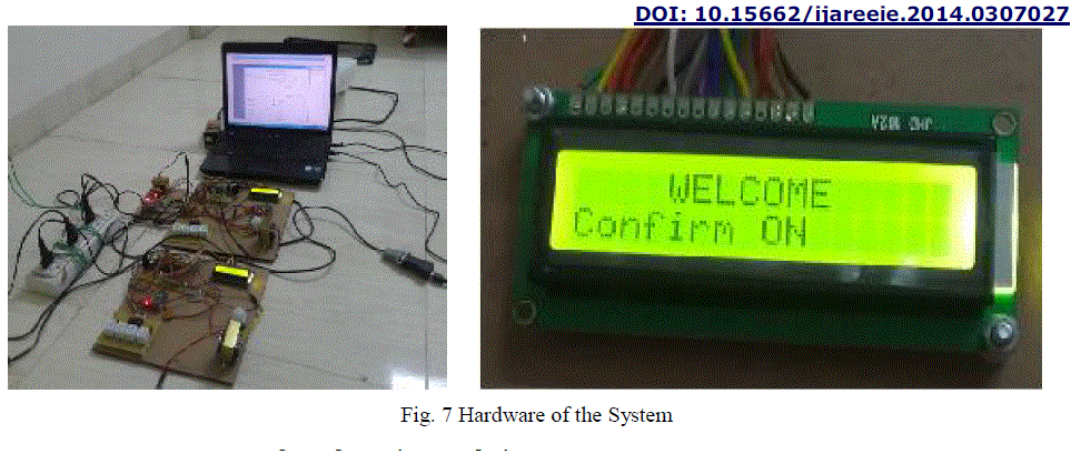
| Fig.7 illustrates the hardware view of the proposed system. A low power and low-cost 16-bit micro controller unit (MCU) is used as the main processor. An RF transceiver module is used for communication. The power supply unit consist of bridge rectifier supplies the power to the MCU and other peripherals by converting AC to DC. The MCU can control a solid state relay on the basis of the signals given by the PIR to MCU. A variety of information such as operating mode, light intensity, temperature are displayed via a LCD. |
 |
IV EXPERIMENTAL RESULTS |
 |
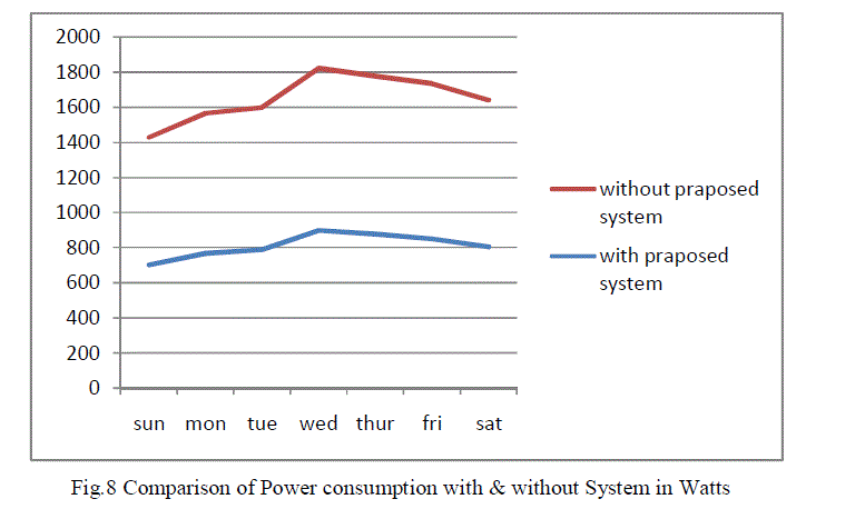 |
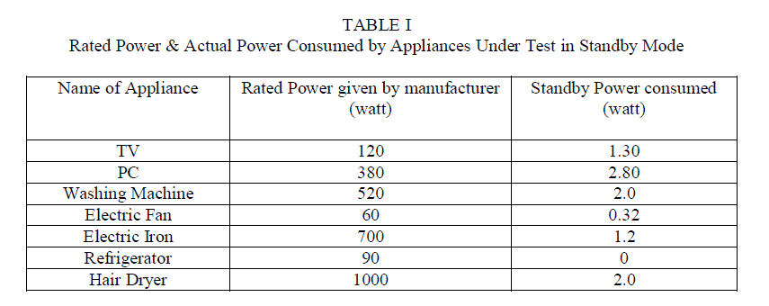
| The above graph shows the comparison between power consumption with and without the proposed system. If the the proposed system is implemented then 10% -20% power can be saved and it will reduces the electricity bill too. |
V. CONCLUSION |
| The home appliances have become more efficient causing a continual decrease in leakage power consumption in recent years. The total leakage power is continuously growing in the future as the number of home appliances is increases. In this paper, we proposed and implemented a new control system that decreases the standby power to absolute zero power. The thought is to sense the voltage in actual operating condition and in standby condition and then disconnect the device from mains ac source. Implementing this idea in a commercial appliance, a zero leakage power system can be constructed. As PV cell efficiency is improving these days, the laser aiming time and operation distance will be further improved. It is expected that this proposed system will be applied to all the appliances which are controlled by remote in order to conserve energy and save the environment. Although the standby power of electric home appliances is of that much amount that, it affects the user’s electricity bill in the long run. In this paper we propose a design which reduces the standby power substantially. In the long run our design saves more power. Furthermore, our design, which is equipped not only with a current/voltage sensor circuit and an MCU to control leakage power but also it can be modified by programming and can then be applied to a new generation of appliances to save even more power. |
References |
|