ISSN ONLINE(2278-8875) PRINT (2320-3765)
ISSN ONLINE(2278-8875) PRINT (2320-3765)
G. Hima Bindu1, Dr. P. Nagaraju Mandadi2
|
| Related article at Pubmed, Scholar Google |
Visit for more related articles at International Journal of Advanced Research in Electrical, Electronics and Instrumentation Engineering
This paper describes the performance comparison of a wind power systems based on three different induction generators. The three induction machines studied for the comparison are the squirrel-cage induction generator (SCIG), the doubly fed induction generator (DFIG) and using a doubly fed induction generator in single-sided grid connection. The performances are compared between the SCIG, DFIG and DFIG in single-sided grid connection systems. The SEF-DFIG stator of the machine is connected with a direct power grid, and the rotor is controlled by an inverter without any external power source. In this paper, for applying the proposed scheme to the wind turbine, the design and modelling of the induction generators simulated in MATLAB/SIMULINK environment
Keywords |
| Doubly fed induction machines, field oriented control schemes, wind power system. |
I.INTRODUCTION |
| WITH a shortage of fossil fuels and global concerns for environmental sustainability, the demand for renewable energy is increasing steadily. Wind energy conversion system is generally connected to the electric power grid and supplies electric power to supplement the base power from other generation systems using fossil fuel or nuclear energy. The increasing emphasis on renewable wind energy has given rise to augmented attention on more reliable and advantageous electrical generator systems. Induction generator systems have been widely used and studied in wind power system because of their advantages over synchronous generators. Induction generator is a asynchronous generator, it is a type of AC electrical generator. Induction generators operate by mechanically turning their rotor faster than the synchronous speed. These are useful in applications such as mini hydro power plants and wind turbines. Induction generators are mechanically and electrically simpler than other generator types. Induction generators are particularly suitable for wind generating stations as in this case speed is always a variable factor. Unlike synchronous motors , induction generators are load dependent and cannot be used above for grid frequency control. The straightforward power conversion technique using squirrel-cage induction generator (SCIG) is widely accepted in fixed-speed applications with less emphasis on the high efficiency and control of power flow. Another major problem with SCIG power system is the source of reactive power. On the other hand, the doubly fed induction generator (DFIG) with variable-speed ability has higher energy capture efficiency and improved power quality. With the advent of power electronic techniques, a back-to-back converter, which consists of two bidirectional converters and a dc link, acts as an optimal operation tracking interface between generator and grid. |
| Although high robustness, reliability, and low maintenance cost are the advantages of this system, it is a demerit that the machine speed and the generated power are not controllable but simply determined by the wind speed. These types of WECSs can reduce the power fluctuations due to the wind speed changes, and it is also possible to achieve maximum power points tracking (MPPT), because the back-to-back pulse width modulation (PWM) converter controls the generated power. This paper proposes a configuration of single external feeding of DFIG (SEF-DFIG) where a rotor-side inverter. The power consumed in the rotor-side inverter is supplied from the stator windings connected to the grid. Since the SEF-DFIG can also control the torque, power, and speed of wind generator as in the conventional DFIG and operate in variable-speed mode and regulate the generated power in various wind speed. The main focus of this paper is the modelling comparisons between the three induction generator wind power systems. |
II. SCIG WIND POWER SYSTEM |
| The schematics of the SCIG system including the wind turbine, pitch control, and reactive power compensator. The entire system includes three stages for delivering the energy from wind turbine to the power grid. The first one is wind farm stage which handles with low voltage, the second is distribution stage which has medium voltage, and the third is grid transmission stage which has high voltage. The three-phase transformers take care of the interface between stages. As mentioned, nominal power Pn SCIG is considered as active power reference to regulate the pitch angle while Vdis and Idis denote the distribution line-to-line voltage and phase current, and they are monitored to favour the reactive power compensation for distribution line. This fairly straightforward technique was first used since it is simple and has rugged construction, reliable operation, and low cost. However, the fixed-speed essential and potential voltage instability problems severely limit the operations of wind turbine. Since SCIG is of fixed-speed generator, for a particular wind speed, the output active power is fixed as well. Thus, with the increase of wind speed, so does the output power until the nominal power is reached. The wind speed at this moment is called nominal wind speed. |
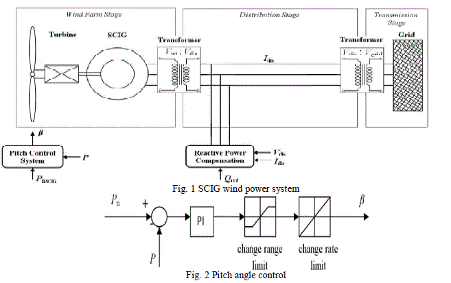 |
| A proportional integral (PI) controller is used to control the blade pitch angle in order to limit the electric output power to the nominal mechanical power. The pitch angle is kept constant at zero degree when the measured electric output power is under its nominal value. When it increases above its nominal value the PI controller increases the pitch angle to bring back the measured power to its nominal value. |
III. DFIG WIND POWER SYSTEM |
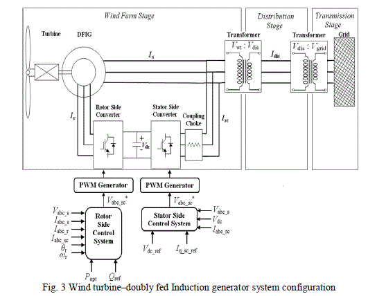
| The dynamic slip control is employed to fulfil the variable-speed operation in wind turbine system, in which the rotor windings are connected to variable resistor and control the slip by the varied resistance [1],[3]. This type of system can achieve limited variations of generator speed, but external reactive power source is still necessary, to completely remove the reactive power compensation and to control both active and reactive power independently, DFIG wind power system is one of most popular methods in wind energy applications [1], [3],[7]. In particular, the stator-side converter control involving an RL series choke is proposed. Both controlling of rotor- and stator-side converter voltages end up with a current regulation part and a cross-coupling part. The wind turbine driving DFIG wind power system consists of a wound-rotor induction generator and an ac/dc/ac insulated gate bipolar transistor (IGBT)-based pulse width-modulated (PWM) converter (back-to-back converter with capacitor dc link), as shown in Fig. 3. In this configuration, the back-to-back converter consists of two parts: the stator-/grid-side converter and the rotor-side converter. Both are voltage source converters using IGBTs, while a capacitor between two converters acts as a dc voltage source. |
 |
IV.SEF-DFIG WIND POWER SYSTEM |
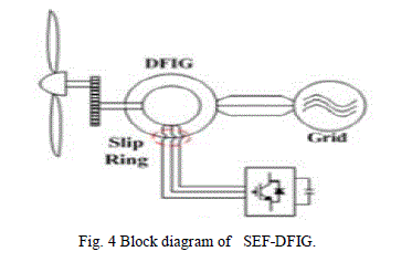
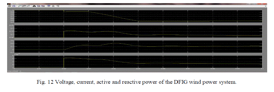
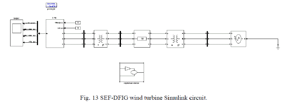
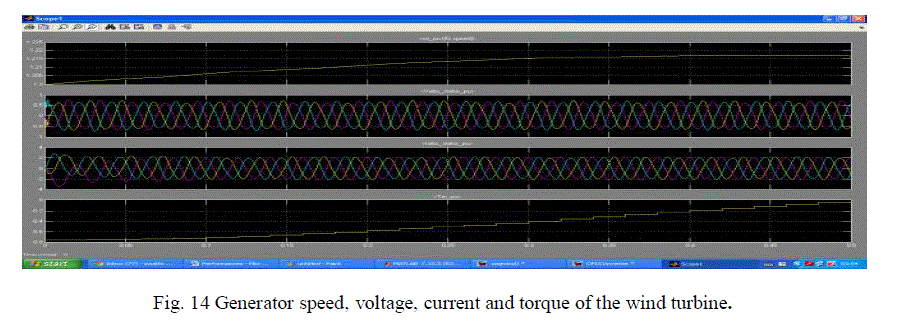
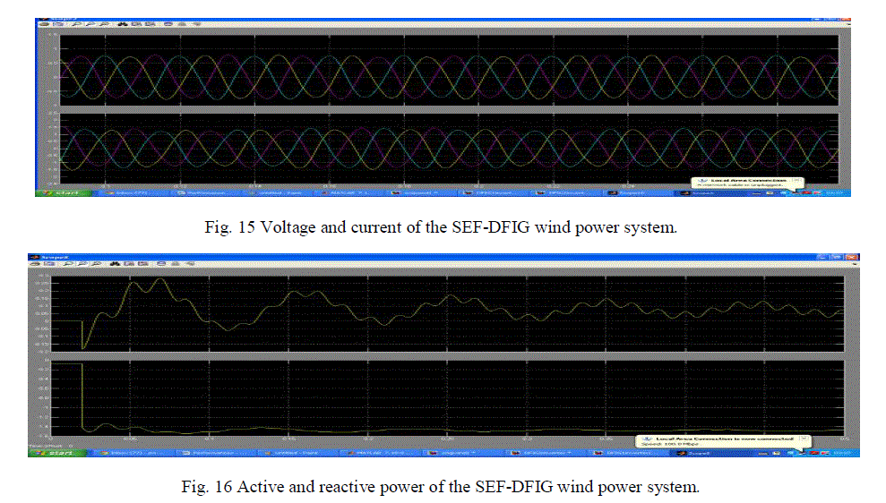
| In SEF-DFIG wind power system is same as that of DFIG wind power system but the stator of the machine is connected with a direct power grid and the controlling of rotor directly connected to inverter without any eternal power source. This is known as single external feeding of DFIG uses an additional grid power converter to regulate the rotor power; but in SEF-DFIG, the external source of a grid power is only connected to the stator windings. Due to this feature, the rotor-side inverter can be integrated on the rotor without any slip ring. |
 |
V. SIMULATION RESULTS |
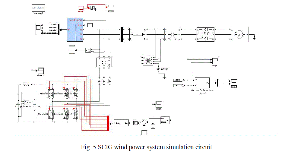 |
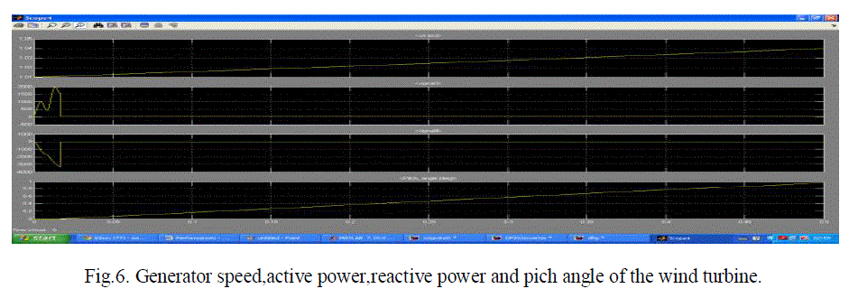
| Fig.6 shows the wind step response of generator speed, active power, reactive power and pitch angle from the above SCIG wind power system Simulink model. |
 |
 |
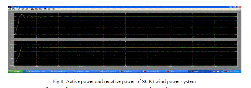 |
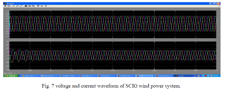
| Fig(7)and (8) shows the voltage, current , active power and reactive power of the SCIG wind power system . |
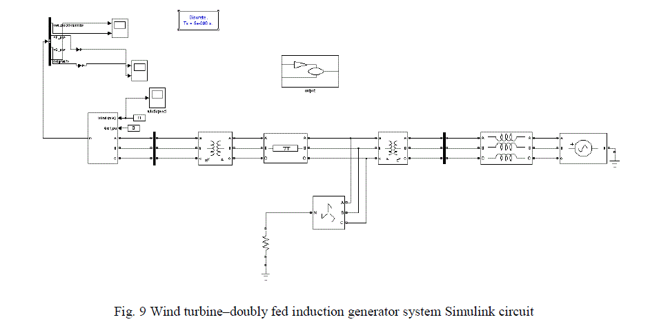 |
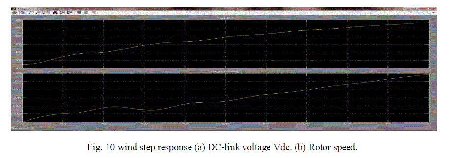
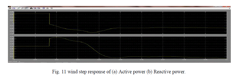
| Fig (10) and (11) shows the wind turbine step response of DC-link voltage, rotor speed, active power and reactive power . |
 |
 |
 |
 |
 |
 |
V.CONCLUSION |
| The induction machines studied for the simulation comparison are the squirrel-cage induction generator (SCIG), the doubly fed induction generator (DFIG) and using a doubly fed induction generator (DFIG) in single-sided grid connection. These induction generators are modelled and simulated in MATLAB/SIMULINK environment. The performances compared between the SCIG, DFIG and DFIG in single-sided grid connection systems. In this paper, for applying the proposed schemes to the wind turbine, the design and modelling comparisons are analysed. |
References |
|