Glass has evolved as one of the primary structural material used all over in construction. The creative use of glass in construction has become a trend with many Indian architects with manifold of technical advancements and continuous improvements of the use of glass in modern buildings. Although glass adds to the aesthetic appeal of a structure, it has serious drawbacks that are often not considered. One of the most obvious drawbacks of glass facade is that it traps heat. The glass facade increase indoor temperatures and invariably in the cooling load on the building air conditioning. As a result of that the energy consumption increases, subsequently in an overall energy scarcity. High performance glass of double glazing or double skin facade with adequate coatings and sensible architecture has to be integrated into the design. The general aim of this work is to design the structural double glazing facade as per Indian Standard draft code and also contribute to the performance assessment on Thermal energy aspect. In order to evaluate the energy performance of structural double glazing, the model was implemented in Comsol Multiphysics simulation software. The results from this study indicates that by using Double-skin facades it is possible to improve the overall building‟s energy use. Most typologies of double skin facade such as low-E glass is capable of lowering the cooling demand and rely on natural ventilation and light simultaneously, which is the norm today.
Keywords |
| Double glazing facade, Heat Strengthened Glass, Insulated Glass Unit, Thermal performance, Cooling
load reduction, Facade technology, Comsol Multiphysics |
INTRODUCTION |
| The building skin is a vitally important architectural consideration. No other building system combines as significant an
impact to both a building‟s performance and aesthetic. The use of glass as a component of the building envelope has
been increasing since its initial introduction as a building material, accelerating in the twentieth century owing to the
development of high-rise steel framing systems and curtain wall cladding techniques. Little has changed in the core
technology of glass curtain walls and facades since their initial development. Much has changed, however, in the
building arts in the past decade alone in terms of aesthetic and performance drivers, as well as in available structural
systems and materials. In response to these market forces, new glass facade types have emerged in spot applications
over the past two decades. These new facade designs play off the primary attribute of glass, its transparency, and
increasingly off the structural properties of glass and the integration of glass components into the structural system.
Characteristics of this technology include, highly crafted and exposed structural systems with long-spanning capacity,
integration of structure and form, simultaneous dematerialization, complex geometries, extensive use of tensile
elements, specialized materials and processes, an integration of structure and cladding system, and a complex array of
design variables ranging from facade transparency to thermal performance and bomb blast considerations. There are
several ideas directly related to the facade of a building that allow for utilization of the external environment to
maintain the indoor comfort. Among these proposals there is the double skin facade, which creates the extra protection
for the building and utilizes solar radiation and wind pressure in order to ventilate, heat or cool down the building. In
this way the facade of the building is not just a closure of the building but becomes an “Energy Supplier” and an
“Energy Manager”. Furthermore, the limitations of fossil fuels in the earth and air pollution are global reasons to
stimulate energy savings. Sustainable approach, which consume minimum amounts of natural resources during
construction, operation and demolition processes. |
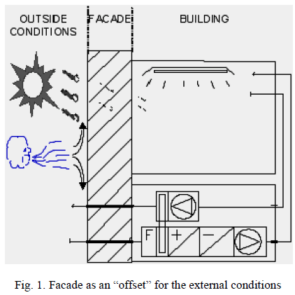
| Moreover, the function of the facade was traditionally recognized as a passive insulation between the interior and
exterior and used to act as a sort of barrier from the external conditions. Thus, the facade had to cut off any influences of the outside temperature, sun and wind on the indoor climate. Currently, utilization of natural sources in buildings is
regarded as a main possibility to decreasing energy consumption. Such an attitude highlights the importance of the
facade, which can be considered as a buffer between the exterior and interior that takes an active part in control of the
indoor environment. The facade utilizes the energy of the sun and wind in order to supply daylight and natural
ventilation to the building, what decreases the capacity and energy consumption of the installations. The figure.1
illustrates the facade as an offset and serving as an active member for external and internal environments. |
 |
MATERIALS USED FOR STUDY |
| There are range of solutions for commercial glazing that provides solar control, thermal insulation and better acoustics.
Glass balances light, transparency and appearance with the practical functions of thermal insulation, solar control,
safety and security, acoustic insulation, fire protection, etc. As a building material, glass is highly versatile and can be
processed in several ways; it can be toughened, bent, laminated or insulated. Using glass facades, it is possible to link
interior space to exterior with minimum compromise. In a tropical country like India, glass facades can control the
amount of heat that enters buildings. Incorporating heat strengthened double glazing will enhance the thermal
insulation and noise attenuation. Figure 2 depicts the general arrangement of Insulated glazing units (IGUs) with
various components to control indoor temperature. |
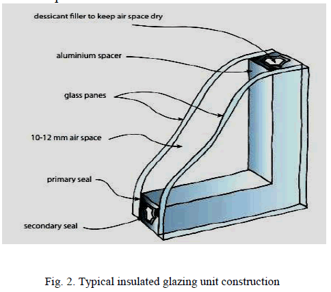 |
| Insulated Glass, often called double glazing, is a combination of two or more panes of glass spaced apart with a spacer
bar and hermetically sealed with a primary and secondary sealant to form a single unit with one or more air spaces in between. IG units improve the thermal performance, thus significantly reducing heating and air-conditioning costs. IG
units also reduce probability of condensation formation on the surface of the glass.IGU can be a combination of Low-E
coatings, tinted glasses, reflective coatings, silk-screened patterns, laminated glass products and more. A wide variety
of insulating glass configurations satisfy a variety of performance and aesthetic requirements. A double-glazed IGU
typically consists of two sheets of glass spaced apart, typically with a hollow aluminium frame that is sealed to both
panes. The space between the panes may contain dry air, or be a partial vacuum, or be filled with argon gas. Here in
this study, Heat strengthened glass has been taken up as glass panes with aluminium frame and air gap is filled using
argon gas. The characteristic features of materials used has been explained in subsequent sections. |
| A. Characteristics of Heat Strengthened Glass |
| Heat-strengthened glass provides higher resistance to thermal stress when compared to annealed glass. When producing
Heat-strengthened laminated glass in comparison with Tempered Laminated glass, Heat-strengthened glass allows the
interlayer to laminated glass to adhere more evenly because of a flatter finish surface. As against toughened glass,
Heat-strengthened glass - with its flatter surface - also results in the facade having less optical distortions. This glass is
difficult to break compared to ordinary annealed glass, but unlike toughened safety glass, breaks typically edge to edge
and in fragments. Heat-strengthened glass is typically specified when additional strength is needed to resist wind
pressure, thermal stress or both and the additional strength or safety break pattern of fully tempered glass is not
required. Another advantage of heat-strengthened glass is that when broken, the glass fragments are more similar in
size and shape to annealed glass fragments and thus tend to stay in the opening longer than fully tempered glass
particles. Although heat-strengthened glass is not a safety glazing by building code, this breakage pattern prevents the
glass from falling and injuring someone. |
| B. Characteristics of Argon Gas |
| Heat transfer through windows can be reduced by using argon gas between the panes of double glazing. Argon gas is a
low-cost, clear, non-toxic, naturally occurring gas with a lower thermal conductance than air. Use of argon between
glazing panes instead of air can reduce the amount of heat conducted across the gap and improve the R-value
performance by approximately 15%. Argon also substantially improves the R-value of IGUs where the gap between the
panes is narrower than the recommended 10 mm minimum. Argon, which has 34% lower thermal conductivity than air,
is the most commonly used. Although argon-filled units cost around 5% more than air-filled units, they can improve a
double glazing window‟s U value or energy rating by over 30%. Argon fillings should last the lifetime of a double
glazing window and over a period of 25 years should not lose more than 5%. |
DESIGN OF STRUCTURAL DOUBLE GLAZING |
| The design covers the selection of glass in buildings, subject to wind loading, seismic loading and special
considerations for fire rated glass and related materials. While selecting the glass for application, the thickness and type
of glass required shall satisfy thickness of glazing is calculated subjected to wind load as per the provisions of standard.
According to BIS draft code, (Code of practice for use of Glass in buildings Part-3Fire and Loading,
DocNo.CED13(7885)WC) the thickness of the glass to be used in window panels is governed by the following factors: |
| 1. Area to be covered by window panel |
| 2. Support conditions (supported on two sides or four sides). |
| 3. Aspect ratio of panel (length / width). |
| 4. Effective wind pressure |
| 5. Strength of glass |
| 6. Type of glass |
| The step by step procedure to calculate the appropriate thickness of glass panel has been explained with a building case
study to design of Heat Strengthened glass panel dimension size of width 1200mm and height 1800mm supported on
four sides for a 15m high office building located in Chennai in terrain category II. The plan of building is rectangular
with the size as 60x50 m. The permeability of building is between 5% to 20%. The wind pressure has been calculated
using IS 875 (Part 3) 1987. The salient features of procedure are summarized as follows: |
| 1. The maximum area of glass panel is restricted to 15 m2. |
| 2. The maximum span of window is restricted to 4 m. |
| 3. Aspect ratio of the glass panel should be greater than 1.5. If it is less than 1.5, next higher available thickness
should be selected. |
| 4. The factor of safety used is 2.5 considering the variability in strength of glass. |
| 5. Applicable to normal, reflective, laminated, tempered and insulating glass. |
| 6. Applicable to rectangular panels properly fixed. |
| Step 1. Calculation of Aspect Ratio (AR) |
| Aspect ratio( AR max) = Longer side / shorter side of glass |
| Aspect ratio = 1800/1200 = 1.5 |
| Step 2. Selection of Design Wind Pressure (Pz) |
| Pz = 0.6 Vz 2 |
| where, Vz = Design wind speed at any height z in m/s |
| Vz = Vb.k1.k2.k3 |
| Vb = 50 m/s (basic wind speed for Chennai location -50m/s taken from IS 875-Part 3). |
| k1 = 1 (Risk coefficient factor, Table 1, IS 875-Part 3) |
| k2 = 1.02 (Terrain factor, Table 2, IS 875-Part 3) |
| k3 = 1.1 (Topography factor, Table 3, IS 875-Part 3) |
| Vz = 50x1x1.02x1.1 = 56.1 m/s |
| Pz = 0.6 x 56.12 = 1888.3 N/m2 |
| Therefore, Design wind pressure at height H for Chennai location, wind zone V, terrain category II, Class B structure is
1888.3 N/m2. |
| Step 3. Calculation of Net pressure coefficient (Cp) & wind pressure Pnet |
| The value of C p for permeability in the range of 5% - 20 % and l/w = 60/50 = 1.2 being between 1 & 1.5, is 1.7 as per
table. 4, IS 875 (Part 3) 1987. |
| Pnet = Pz x Cp, |
| where, Pz = Design Wind Pressure, Cp = Pressure coefficient |
| Pnet = 1888.3x 1.7 = 3210.1 N/m2 |
| Step 4. Strength Factor (Pf) |
| Based on the types of glass (Laminated/Tempered/Insulating Glass) pressure factor is calculated. To determine the
thickness of laminated / tempered / insulating glass, Pf is the pressure factor dependent on the type of glass. The values
of Pressure factor Pf can be taken from table 2 BIS draft code part 3. For Heat Strengthened glass, Pf = 1.60.The
modified value Pnet , |
| Pnet = Pz/Pf |
| Pnet = 3210.1/1.60 = 2006.3 N/m2 |
| Step 5. Calculation of minimum thickness (supported on all sides) |
| Aspect ratio = 1.5 |
| Area of panel = 1.8 x 1.2 = 2.16m2 |
| Using equation of empirical relationship as given in clause 5.3, (Code of practice for use of Glass in buildings Part-
3Fire and Loading) |
| P net * A = 200.0 * TK (T ≤ 6 mm) … (1) |
| Where, Pnet= Net design wind pressure (N/m2) |
| A = area of glass panel (m2) |
| T = SNT of the normal glass (mm) |
| k = constant (Table 2, Code of practice for use of Glass in buildings Part-3Fire and Loading) |
| When, T = 5mm, K = 1.753, |
| P net * A = 200.0 * TK (T ≤ 6 mm) |
| Pnet = 200 x51.753/2.16 |
| Pnet = 1555.50 N/m2 < 2006.3 N/m2 |
| When, T=6mm, K = 1.765, |
| Pnet = 200 x 61.765/2.16 |
| Pnet = 2187.82 N/m2 > 2006.3 N/m2. |
| Hence, we must provide 6mm thick Heat Strengthened Glass on both sides of glazing. |
PERFORMANCE ASSESSMENT OF STRUCTURAL DOUBLE GLAZING |
| During the design of a building, environmental issues have gained considerable influence in the entire project. One of
the first concerns is to improve thermal performances. Structural double glazing are being more and more commonly
adopted in high-rise office buildings. Their potential lies in their ability to react and adapt to different boundary
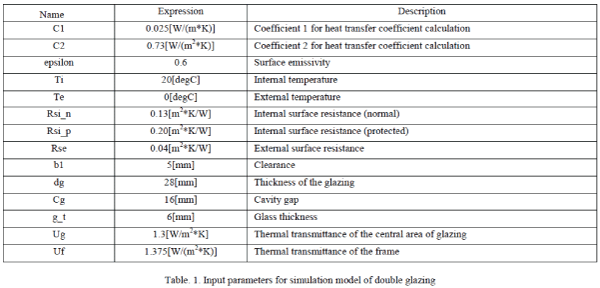
conditions and needs. In order to assess the thermal performance, the simulation model of the double glazing was
implemented in Comsol Multiphysics. The heat transfer with surface-to-surface radiation interface is used to model
heat transfer by double glazing with aluminium frame. The models are executed in 2D for simulating heat conductance
of glazing and 3D for simulating the surface temperature based on external radiation source.. The preprocessing of
input parameter data has shown in table. 1 below. |
 |
| Sophisticated analysis is carried out with models, in which the facade behavior is known with more detail, although
models with different degrees of complexity was found. On the two interface cases, a glazing section separates a hot
internal side from a cold external side. |
| A. Boundary Conditions |
| The heat flux conditions for internal and external sides are given by the Newton‟s law of cooling: |
 |
| where Text is the exterior temperature (Text = Ti = 20 °C for the internal side and Text = Te = 0 °C for the external side).
The standard defines thermal surface resistance Rs, which is related to the heat transfer coefficient h by: |
 |
| Internal and external thermal surface resistances are not equal. Furthermore, two boundaries are considered as adiabatic:
the boundary in contact with the wall and the end of the glazing. |
| B. Description of models |
| 1. 2D model- The glazing is made of two glass panels with a thermal conductivity of 1.00 W/(m·K). On the
frame side of the glazing, a structure made of aluminum, polysulfide, and silica gel is used to block the glass blocks.
Their thermal conductivities are 160 W/(m·K), 0.40 W/(m·K), and 0.13 W/(m·K), respectively. The space between the
glass panels is filled with argon gas whose thermal conductivity is 0.0164 W/(m·K).This model is computed for heat
transfer in solids interface to determine the Thermal conductance of glazing and Linear thermal transmittance of the
frame. |
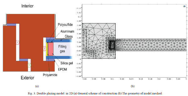 |
| The figure.3.(a) above depicts the general scheme of construction in which regions marked, two cavities are
completely closed and are considered as unventilated and the third one is considered as slightly ventilated. The
geometry of model meshed with free triangular mesh of entities of domain is represented in figure.3.(b). |
| 2. 3D model- The glazing with 28 mm thickness which is partitioned as 6mm glass panes and cavity of 16mm for
thermal insulation. It is modelled using Autocad 3D and imported to Comsol Multiphysics simulation software to
execute the surface to surface radiation where the external radiation source is considered to be sun's intensity defined
by its solar position to a specific location. the surface temperature over the glazing surface is computed for the results
which is explained in subsequent chapter. |
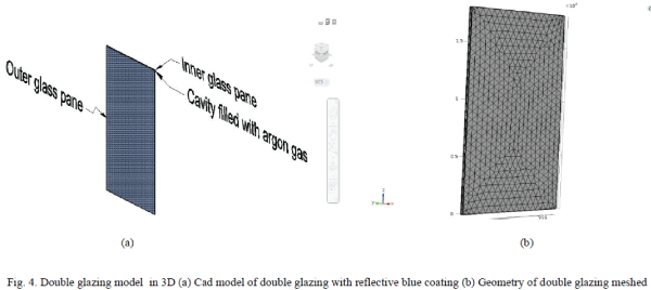 |
| The figure.4.(a) shows the 3D cad model of structural double glazing with Reflective blue colour texture as material. It
comprises two glass panes separated with cavity filled with argon gas and figure.4.(b) illustrates the 3D model with
Free Tetrahedral mesh using Comsol Multiphysics simulation software. |
RESULTS AND DISCUSSION |
| The performance assessment of structural double glazing was computed using Comsol Multiphysics software with two
physics interfaces, Heat transfer in solids with 2D model and Surface to surface radiation with 3D model. |
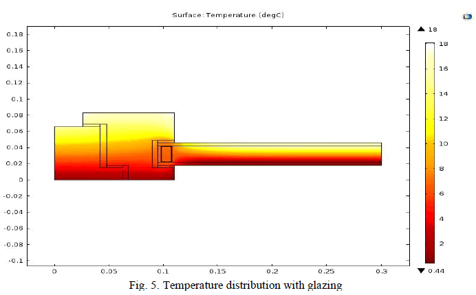
| A. Heat transfer in solids- The thermal conductance of the entire section and the linear thermal transmittance of the
frame Ψ is evaluated. The thermal conductance of the Section is found to be 0.482 (W/(m*K)) and thermal
transmittance of the frame Ψ is evaluated to be 0.085(W/(m*K)).The temperature profile of section is exhibited in
figure.5 below . |
 |
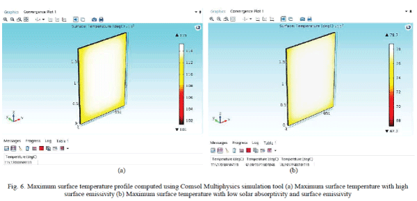
| B. Surface-to-surface radiation- The model with surface emissivity 0.6 is simulated to determine the surface maximum
temperature on diffuse surface of outer glazing and value is found to be 115.17(deg C).The same model is then
simulated with solar and ambient wavelength dependence of emissivity in which solar absorptivity and surface
emissivity is entered as 0.4 and 0.6 respectively. The results found to be sudden fall in maximum surface temperature to
92.09(deg C). Further, interpreting the emissivity wavelength parameter of diffuse surface consequently there is a abrupt change with maximum surface temperature to 78.69(degC) which ultimately reduce the cooling load in indoor
condition. The comparison of maximum surface temperatures are represented in figure.6. It is evident that figure.6.(a)
below portrays maximum surface temperature to be 115(deg C) and subsequently diminishing to 78(deg C) as shown in
figure.6.(b) due to reducing the wavelength of surface emissivity and solar absorptivity properties. |
 |
CONCLUSION |
| The use of structural glass allows the creation of transparent and translucent structures. This has the advantages of
creating buildings with a “lightness of appearance” and internal spaces that benefit from the resulting natural daylight.
Glass has become an accepted structural facade material by following standards that exists to govern the design and
construction of glazing. The design procedure for determining minimum glass thickness has been explained as per BIS
draft code. All results were obtained for Chennai summer climate conditions. Since, Transparent double skin facades
are predicted to increase cooling loads in office buildings in hot arid areas, there is a requirement for an enhanced
strategies for better performance. The performance assessment of structural double glazing is computed using Comsol
Multiphysics simulation software and outcomes of work are summarized as follows: |
| 1. The thermal conductance of the Section is found to be 0.482 (W/(m*K)) and thermal transmittance of the
frame Ψ is evaluated to be 0.085(W/(m*K)). |
| 2. Reduction of maximum surface radiation from 115(deg C) to 78(deg C) by interpreting the solar absorptivity
and surface emissivity of outer glass pane of glazing. |
| This study suggests that due to two panes interrupting the radiation of energy and when using a low-emissivity (low-E)
surface of heat strengthened glass for outer glass pane and cavity with argon gas governs the thermal insulation and
better building energy performances.Therefore, Low-E glass plays an important role in not just significantly reducing
the incoming heat but also decreasing the cost on air-conditioning. It is concluded that an efficient double skin facades
as a facade technology are suitable for reducing air conditioning cooling loads in hot arid climates. |
References |
- Carl M. Lampert, "Chromogenic Smart Materials" , Elsevier Materials today, volume 7, issue 3, pp. 28-35, 2004.
- Eicker. U, Fuxa. V, Bauer .U , "Facades and Summer Performance of Buildings", Energy and Buildings 40, pp. 600–611, 2008.
- Fernando Marques da Silva .A, Gloria Gomes, "Gap Inner Pressures in multi-Storey Double Skin Facades", Energy and Buildings 40, pp. 1553–1559, 2008.
- Giorgi. L, Bertola V, "Thermal Convection in Double Glazed Windows with Structured Gap", Energy and Buildings 43, pp. 2034–2038, 2011.
- Grabe von, J., "A prediction tool for the temperature field of double facades". Energy and Buildings. 34, pp. 891-899, 2002.
- Hasan M. Abdul M.,, Malek A. B. M, " Investigation of Tio2 and Ag Based Single and Multilayer Films for Windows Glazing", ARPN Journal of Engineering and Applied Sciences, Vol. 5, NO. 9, 2010.
- James P.A.B., Bahaj A.S, "Smart Glazing Solutions to Glare and Solar Gain: a „sick building‟ case study", Energy and Buildings 37, pp. 1058–1067, 2005.
- Mehlika N. Inanici, NurDemirbilek F, "Thermal performance optimization of building aspect ratio and south window size in cities having different climatic characteristics of Turkey", Building and Environment 35, pp. 41-52, 2000.
- Mootz, F., J.J. Bezian, "Numerical study of a ventilated facade panel", Solar Energy.57(1) , pp. 29-36, 2007
- NeveenHamza, "Double Versus Single Skin Facades in Hot Arid Areas", Energy and Buildings 40 , pp. 240–248, 2008.
- Rakesh R. Makwana, Prof. M.G. Vanza, "Glass Thickness Determination Using Indian Draft Code", International Journal of Advanced Engineering Technology ,Vol.4, Issue II, pp. 31-33, 2013.
- Stephen R. Ledbetter, Andrew R. Walker, "Structural Use of Glass", Journal of architectural engineering ,Issue 12, pp. 137-149, 2006.
- Saelens D, "Energy Performance Assessment of Single Storey Multiple-Skin Facades", Journal of Applied science, Vol 4, Issue II, pp. 46-51, 2002.
- Terri Meyer Boake, "Hot Climate Double Facade: Avoiding Solar Gain", Facade Tectonics Journal, Volume 14, pp. 68-73, 2009.
|