ISSN ONLINE(2278-8875) PRINT (2320-3765)
ISSN ONLINE(2278-8875) PRINT (2320-3765)
R. Sasikumar1, M. Arounassalame2
|
| Related article at Pubmed, Scholar Google |
Visit for more related articles at International Journal of Advanced Research in Electrical, Electronics and Instrumentation Engineering
Voltage fed single stage converters suffer from two main drawbacks: The efficiency is affected due to the reduced values of maximum DC link capacitor voltage and the power factor is not close to unity. To overcome these drawbacks, a boost type - input current shaping converter, integrated with diode clamped topology is used. Since this converter is a multilevel converter, it can be operated with high DC bus voltage. The power factor is also maintained close to unity. This converter is made to operate with fuzzy logic controller to regulate the output voltage. The fuzzy logic controller is designed and the performance of the ac-dc converter is tested using MATLAB/SIMULINK based closed loop simulation.
Keywords |
| AC-DC power conversion, single-state power factor correction (SSPFC),three level converters. |
I.INTRODUCTION |
| The ac-dc converter are required to have some sort of power factor correction (PFC) capability to meet the harmonic standard such as IEC-1000-3-2 and IEC -1000-3-4. In general there are several PFC techniques that can be used to for removing the input current harmonic [1, 3, 4, 5]. There are two main methods to reduce the input line current harmonic are passive PFC converters and active PFC converters. Passive PFC converters are the simplest and most straight forward methods to reduce input current harmonic by using passive circuits. The main drawback is that they make the converter heavy and bulky which can be used in limited number of application. Active PFC converters have many advantages over a passive PFC such as high power factor, lower harmonic content, and small converter due to ability to use high switching frequencies. The active PFC can be classified into two stage and single stage PFC techniques. |
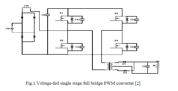
| The two stage techniques uses separate DC/DC converter to perform the input current shaping. Although the two stage PFC approach has many advantages, it has some drawback. It has two power states and hence two control circuits are needed. It is inefficient and is not cost effective as in case of low power application. The drawback associated with two stage PFC method motivated several researchers to find other way to provide both input current shaping and voltage regulation. Thus a new class of single stage power factor correction (SS-PFC) topologies has been presented [6, 7, 8, 9].The voltage fed, single stage PWM full bridge converter shown in fig. 1 seen to be the most promising single stage converters. Voltage fed single stage converters proposed in [2] suffers from two main drawbacks: (i) The efficiency is affected due to the reduced values of maximum DC link capacitor voltage; (ii) The power factor is not close to unity To overcome these drawbacks, a boost type - input current shaping converter, integrated with diode clamped topology is presented in [10].Since the presented converter is a multilevel converter; it can be operated with high DC bus voltage. The power factor is also maintained close to unity. This converter is made to operate with fuzzy logic controller to regulate the output voltage.This paper focus on implementing closed loop control algorithm using fuzzy logic controller for the single stage three level AC-DC converter. The implementation is done using MATLAB/SIMULINK package. The performance of the fuzzy logic controlled system is tested under input voltage variations and output load variations. |
 |
II.CONVERTER OPERATION |
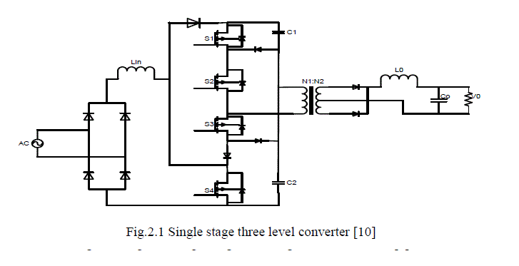
| The single stage three level converters proposed in [10], is shown in fig.2.1, integrates an ac-dc boost PFC converter with a three level dc-dc converter. The ac-dc boost section consist of an input diode bridge,boost inductor Lin ,boost diode D1 and switch ,which is shared by the multilevel dc-dc section .This section is a conventional three level converter except for diode D2 which prevents input current from flowing to the mid-point of capacitor C1 and C2, and D1, which bypasses D2. |
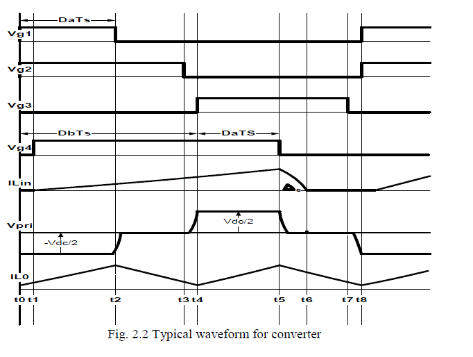
| Although there is only a single converter, it is operated with two independent controllers. One controller is used to perform PFC and regulate the voltage across the primary-side DC bus capacitors by sending appropriate gating signals to S4. The other controller is used to regulate the output voltage by sending appropriate gating signals to S1 to S4. It should be noted that the control of the input section is decoupled from the control of dc-dc section and thus can be designed separately. The gating signal of S1, however, is dependent on that of S4, which is the output of the input controller; how this signal is generated is discussed in detail in the paper. The gating signals for S2 and S3 are easier to generate as both switches are each ON for half a switching cycles, but are never ON at the same time. Typical converter waveforms are shown in fig.2.2, and equivalent circuit diagram that show the converter’s modes of operation are shown in fig 2.3 with diode bridge rectifier output replaced by a rectified sinusoidal source. |
 |
| As the input line frequency is much lower than the switching frequency, it is assumed that the supply voltage is constant within switching cycles. It is also assumed that the input current is discontinuous, although it can be made to be continuous if desired. The converter has the following modes of operation [10]: |
| Mode 1 (t0<t<t1): During this mode, switch S1and S2 are ON and energy from the dc-link capacitor C1 flows to the output load. Since the output section, a positive voltage of (Vpri/N)-V0 is impressed across Lo and the current through it rises |
| Mode 2 (t1<t<t2): This mode is the same as the previous mode except that S4 is turned ON at the start and the voltage across the input inductor (Lin) is the rectified supply voltage and the inductor current increases. The supply voltage can be considered to be constant within a switching cycle as the switching frequency is much higher than the line frequency. |
| Mode 3 (t2<t<t3):S1 is turned OFF at the start of this mode and the primary current of the main transformer circulates through diode Da and S2.The current through output inductor Lo freewheels in the secondary of the transformer during this mode and theinput current through Lin continues to rise. |
| Mode 4 (t3<t<t4): In this mode, S1 and S2 are OFF and S4 is ON. The current in the primary of the transformer charges capacitor C2 through the body diode of S3 and D3. |
| Mode 5 (t4<t<t5): In this mode S3 and S4 are ON. Energy flows from capacitor C2 into the load while the current flowing through input inductor Lin continues to rise. |
| Mode 6 (t5<t<t6): S4 is turned OFF at the start of this mode. The current through input inductor flows through the diode D1 to charge the capacitors C1and C2.The current in the transformer primary flows through the S3 and D2.Also during this mode, the output inductor current freewheels in the secondary of the transformer. |
| Mode 7(t6<t<t7): In this mode, the load inductor current freewheels through the secondary of the transformer. This mode ends when the switch S3 turn off. |
| Mode 8 (t7<t<t8):S4 is turned OFF at the start of this mode and the current in the primary of the transformer charges capacitor C1 through the body diodes of S1 and S2.The converter re-enters Mode 1 after this mode. |
 |
III.FUZZY LOGIC CONTROLLER |
| A. Basic of Fuzzy logic controller |
| Fuzzy logic system is easy to understand, simple to design and better than using the other type of controller. Fuzzy logic allows modeling of complex system that comes from the knowledge and experiences by combining alternative way of thinking using a higher level of abstraction. The variable of fuzzy logic is described for the control algorithm that influences the system variable and a rule table. The fuzzy logic controller has two methods: (1) Mamdani Fuzzy inferences (2) Takagi-Sugeno-Kang. |
| The Mamdani method is widely used and easy for capturing expert knowledge. It describe the expertise in more a human manner. Usually the Mamdani fuzzy inferences process is present in four steps which are: |
| Fuzzification of the input variable |
| Rule evaluation |
| Aggregation of the rule output |
| Defuzzification |
| The triangular membership function is used for the FLC for easier computation. A five term fuzzy set, Negative Big (NB),Negative small (NS),Zero (ZE),Positive small(PS),Positive big(PB) is defined for input variable and for output variable the fuzzy set are small(S),medium(M),Large(L). This is describedas linguistic variables. fig3.2 shows the membership functions of the input and output variables of the fuzzy system. The value of each input variable is normalized in the range [-10, 10] and output variable is normalized in the range [0, 0.5] by using suitable scale factor. The symmetrical distribution of membership function can generally be represented as follow: |
| Input variable: Output Variable: |
| NB: [-15,-10, -5] S: [-0.2, 0, 0.15] |
| NS: [-10,-5, 0] M: [0.05, 0.25, 0.45] |
| ZE: [-5, 0, 5] L: [0.25, 0.5, 0.7] |
| PS: [0, 5, 10] |
| PB: [5, 10, 15] |
 |
| B.Fuzzy logic rules |
| Fuzzy controller rules which play a very important role for controller design are obtained from the analysis of the system behaviour. In their formulation it must be considered that, by using this controller we improve the converter performances in terms of dynamic response and robustness. |
| Rule 1: If error is NB then Duty ratio is M |
| Rule 2: If error is NS then Duty ratio is M |
| Rule 3: If error is ZE then Duty ratio is S |
| Rule 4: If error is PS then Duty ratio is M |
| Rule 5: If error is PB then Duty ratio is L |
IV.CONVERTER DESIGN |
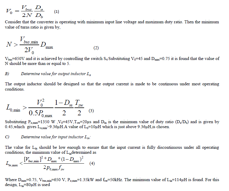
| A procedure for the design of the converter proposed in [10] is presented in this section. The converter is designed with the following parameters: |
| 1) Input voltage :Vin=90-265 Vrms; |
| 2) Output voltage:V0=45; |
| 3) Maximum output PowerP0=1.35K; |
| 4) Switching frequency fsw=50kHz; |
| A) Determine value for turns Ratio of main Transformer N: |
| The relation between Vbus, D, V0, and N is |
 |
V. SIMULATION RESULT |
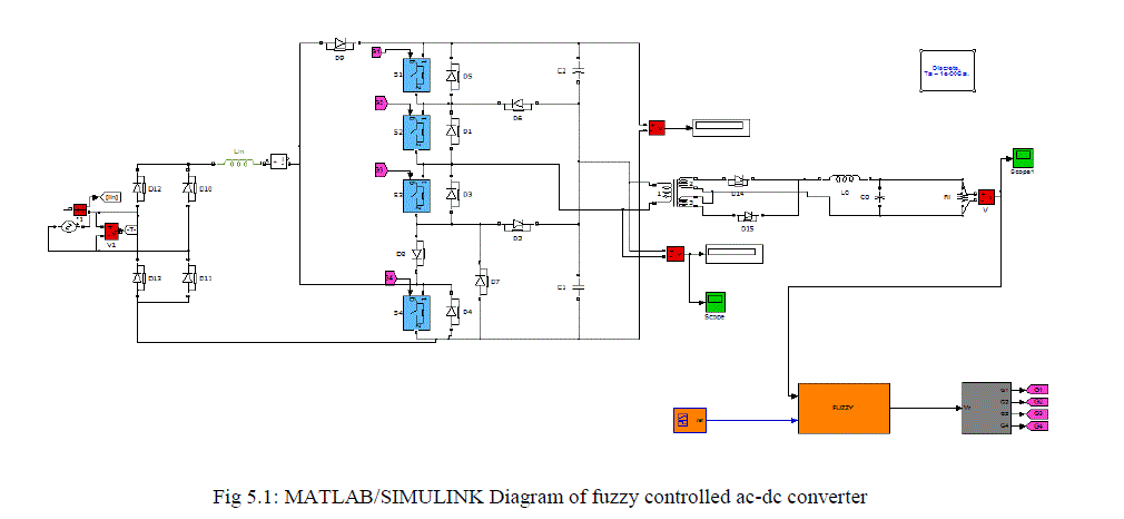
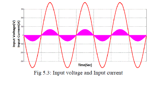
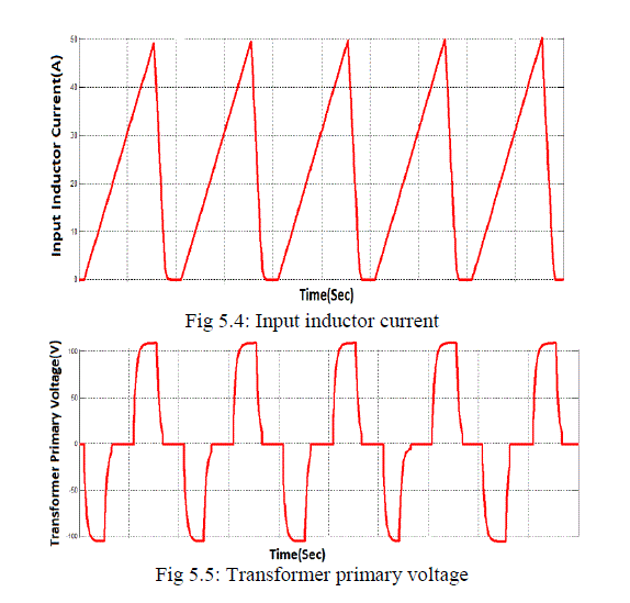
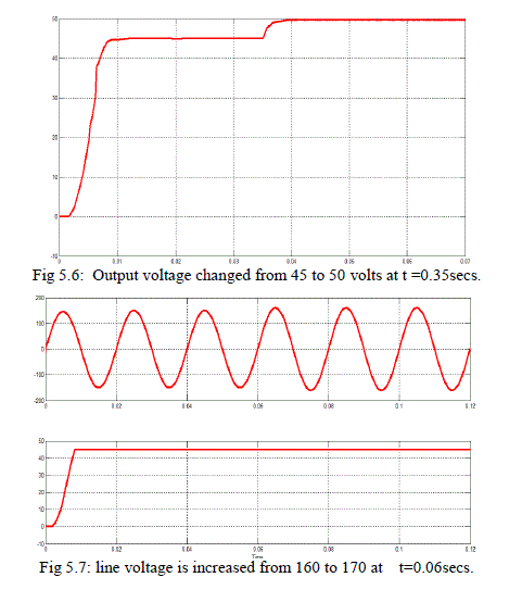
| The single stage three level ac-dc converters with fuzzy logic controller is simulated using MATLAB/SIMULINK. The SIMULINK diagram is shown in fig (5.1). The performance was analysed for the input voltage ranging from 90-265 volts. The other parameters used for simulation are Lin=10μH, Lo=80μH,C1=C2=2200μF and the turn ratio is taken as 5:1.The simulation results are shown in Fig5.2 to fig 5.7. Fig. 5.2 shows the gating waveform for the switch S1,S2,S3 and S4. Fig. 5.3 shows the input voltage and input current waveforms.It can be seen that both the waveforms are in phase and there is no dead-band region in the input current. Fig 5.4 shows the current waveform of input inductor of multilevel converter. Fig. 5.5 shows the typical voltage across the primary side of the main transformer. Fig. 5.6 shows output voltage at full load condition.The tracking performance of the fuzzy logic controller is illustrated by varying the reference voltage from 45volts to 50 volts. Fig 5.7 shows the performance of the closed loop system for a variation in input line voltage. |
 |
 |
 |
 |
 |
VI. CONCLUSION |
| A single stage three level ac-dc converter with Fuzzy logic controller was implemented using MATLAB/SIMULINK and its performance was analysed for variations in the input voltage and changes in the output reference voltage.It was observed that the performance of the converter was not affected even when the input voltage changes. Also it was observed that the output of the converter tracks the reference voltage without any appreciable delay. The outstanding feature of this converter is better efficiency, less distorted input current, less output current ripple and finally it combines the performances of two stage converter with reduction of cost of single–stage converters. The hardware implementation of the converter with fuzzy logic controller is under investigation. |
References |
|