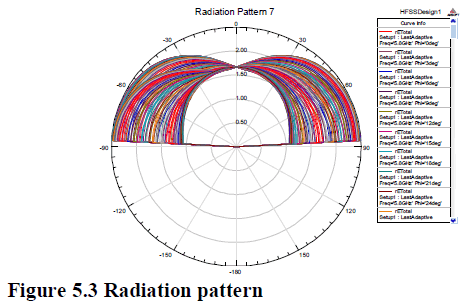
The objective of the project is to design and simulate the planar monopole antenna for UWB applications. The base of the proposed antenna is a diamond-shaped patch (DSP) that covers the ultra wide band (UWB) 3.1–10.6 GHz frequency range. It is shown that by removing the centre part of the DSP antenna, without distorting the UWB behavior. This will not affect the dimension of the base antenna. The used substrate is FR4 with relative permittivity of 4.4 and thickness of 1mm.The designed simple DSP - UWB antenna has a substrate size of 16*22mm2and covers the frequency band 3.1–10.6 GHz which includes UWB. The antennas have omnidirectional and stable radiation pattern. Hence, a rectangular shaped ground plane is designed and will be simulated using ANSOFT-HFSS. The parameters such as return loss, VSWR and radiation pattern are taken
Index Terms |
| Monopole antenna, ultra wide band
(UWB) antenna, wireless communication frequencies |
INTRODUCTION |
| The ultra wideband (UWB) communication
systems have received great attention from both the
academic and the industrial sectors as a result of
commercial systems such as indoor and hand-held
wireless communication. UWB is short distance radio
communication technologies that can perform high-speed
communication with speeds of more than 100 Mbps.
Modern communication systems require a single antenna
to cover Several allocated wireless frequency bands.
Moreover, design of a multi-band antenna which also
covers the UWB range without deteriorating the UWB
performance is of high interest |
| The objective of this project is to design and
simulate a small-size microstrip-fed UWB base
diamond-shaped-patch (DSP) antenna for multi band
applications using ANSOFT – HFSS. The performance
and behavior of the antenna is analyzed using the results
obtained from the simulation process. |
| The scopes defined for this project are as follow |
| Understanding the antenna concept. |
| Designing the microstrip patch antenna to
operate at UWB frequencies. |
| Performs simulation using ANSOFT / HFSS
software. |
| Obtain results and graphs from the simulation. |
| Analyzing the performance of microstrip patch
antenna. |
| The project begins with the understanding of the
uwb technology. This includes the property studies such
as the radiation pattern, input impedance, return loss,
VSWR, etc. the related literature reviews includes
understanding the previous works done. The design of
the microstrip patch antenna starts with calculating the
dimensions of the patch using the formula. This will
determine the size of the microstrip patch antenna. The
next step is to design the ground plane. |
| The software used for designing and simulation is
ANSOFT -HFSS. Then the measurement was taken and
the graphs are plotted to analyze the performance of the
microstrip patch antenna. |
RELATED WORK |
| I have observed that the size and shape of the
rectangular microstrip planar monopole antennas have significant impact on the antenna gain. By shaping the
rectangular microstrip in UWB, I have increased the gain
of a rectangular microstrip antenna for as much as -10
dB. Theoretical results are will be verified by
measurements. The computed results presented above
were it will be verified by experimentally. The
enhancement of the antenna gain with the rectangular
microstrip, with respect to the gain for the rectangular
plate. The gain enhancement is presented as a function of
frequency. Were this infers that the observed paper uses
UWB band and the proposed system is designed with
UWB band. |
GENERAL CHARACTERISTICS OF
MICROSTRIP PATCH ANTENNA |
| Microstrip patch antenna was first designed in the
year Bob Munson in 1972. One of the most useful
antennas at microwave frequencies (f > 1 GHz). It
consists of a metal “patch” on top of a grounded
dielectric substrate. The patch may be in a variety of
shapes, but rectangular and circular are the most
common. The patch acts approximately as a resonant
cavity (short circuit walls on top and bottom, open circuit
walls on the sides). In a cavity, only certain modes are
allowed to exist, at different resonant frequencies. If the
antenna is excited at a resonant frequency, a strong field
is set up inside the cavity, and a strong current on the
(bottom) surface of the patch. This produces significant
radiation (a good antenna) |
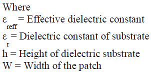
| The formulas used in the design of microstrip patch
antenna are given below, The expression for ε
reff
is given
as; |
 |
 |
| The dimensions of the patch along its length have now
been extended on each end by a distance ΔL; |
 |
| The effective length of the patch L
eff
; |
 |
| Resonance frequency f
o
, the effective length is given by
; |
 |
| Resonance frequency for any TM mode is; |
 |
| Where m and n are modes along L and W respectively. |
| For efficient radiation, the width W is given as; |
 |
MODE OF OPERATION OF MICROSTRIP
PATCH ANTENNA |
| The UWB systems can be divided into two
categories; |
| DS-UWB |
| MB-OFDM |
DESIGN OF MICROSTRIP PATCH ANTENNA |
| A microstrip patch antenna is one whose main
body is composed of two or more sections in which one
of the two sections is mounted over the other. The
bottom larger one may also serve as a supporting stem of
an antenna so as to provide an enhanced antenna system
with a common ground plane. |
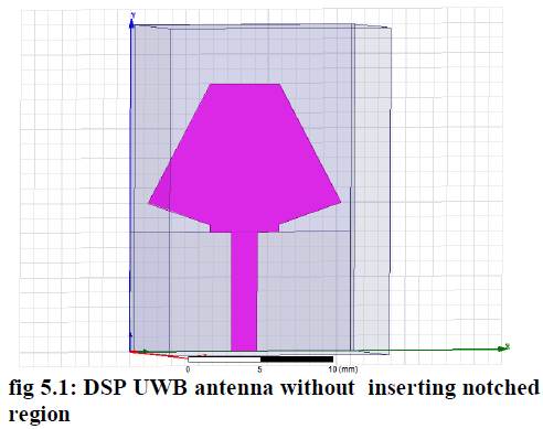
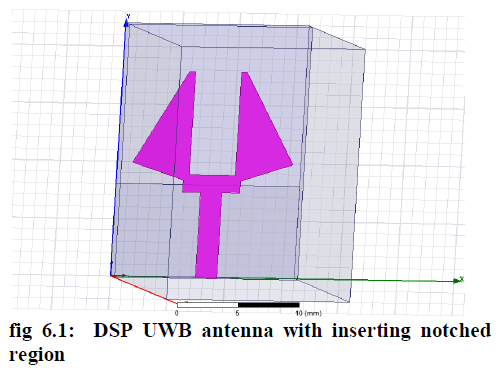
| To design the DSP UWB antenna, DSP antenna with
inserting notched region in the middle part. |
| DESIGN FOR DSP UWB ANTENNA: |
| Given |
| Frequency fr = 9GHz |
| Substrate name: FR4 |
| Substrate size : 16*22*1 mm3 |
| Loss tangent=0.02 |
| εr =4.4 |
| Microstrip-fed line =1.86 mm |
| Characteristic impedance =50Ω |
| DESIGN: |
| From the formula |
 |
| Length L=Leff-2ΔL |
| Resonant frequency: |
| The wavelength is, |
 |
| λ is the free space wavelength, |
| εreff is effective permittivity |
 |
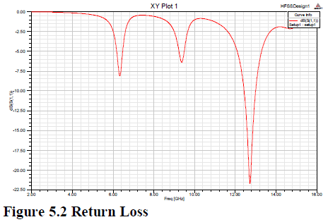 |
| From the return loss graph it is seen that in
frequency at 12.8 GHz it has a value of return loss is -
21.52dB |
 |
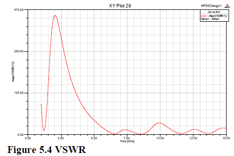 |
| From the VSWR graph it is seen that in frequency at
6.5GHz the value of VSWR is 1 |
DESIGN FOR DSP ANTENNA WITH INSERTING
NOTCHED REGION |
| Design: |
| From the formula |
| Thus, a rectangular section along the axis of the DSP
antenna can be removed as shown in Fig.4.1 (b) without
affecting the overall antenna impedance and radiation
characteristics leading to the UWB antenna |
 |
| Given |
| Frequency fr = 9GHz |
| Substrate name: FR4 |
| Substrate size : 16*22*1 mm3 |
| Loss tangent=0.02 |
| εr =4.4 |
| Microstrip-fed line =1.86 mm |
| Characteristic impedance =50Ω |
| GROUND PLANE DESIGN: |
| Perfect E plane is choose, then set; |
| Axis =z |
| x=16mm |
| y=7.8mm |
| To create the rectangle. |
| Lg=8mm |
| Lf=8mm |
| DSP PATCH DESIGN: |
| Perfect E patch is choosing, then set; |
| Axis =z |
| x=5mm |
| y= -10mm |
| To create the patch. |
| a1=14mm |
| a2=5mm |
| b1=2mm |
| b2=8mm |
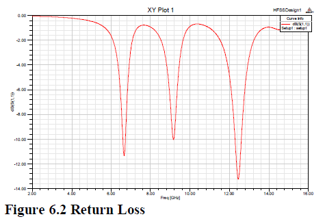 |
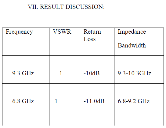
| From the return loss graph it is seen that in
frequency at 6.8GHz it has a value of return loss is -
11.02dB.,9GHz it has a value of -10dB. and 12.3GHz it
has a value of -13.3dB |
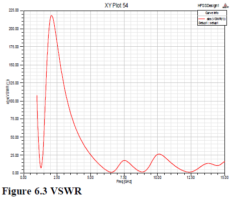 |
| From the VSWR graph it is seen that in frequency at
6.5GHz the value of VSWR is 1. |
 |
 |
CONCLUSION |
| Thus the design and simulation of microstrip patch
array antenna was successfully designed and analysed
using Ansoft/Ansys HFSS. The diamond shaped patch
antenna covers the UWB frequency range. ANSOFTHFSS
software is used to analyze the performance of the
designed antenna. Designed a rectangular microstrip
patch antenna that operates in UWB frequencies. i.e.,
3.1-10.6 GHz frequencies. From observing the return
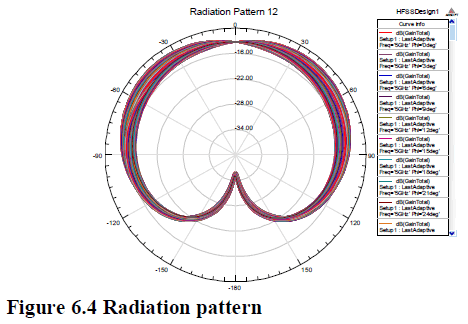
loss, vswr, radiation pattern graphs it is very clear that
this antenna works on the designed UWB frequency
range. Thus the planar monopole rectangular microstrip
patch antenna works in the designed UWB frequency range. When this antenna is implemented it could be
used to transmit or receive signals simultaneously in
UWB frequency range. and design a small-size
microstrip-fed UWB base diamond-shaped-patch (DSP)
antenna for quad band application and to achieve the
UWB frequency band is left for future work. |
References |
- Bernd Schleicher, Member, Ismail Nasr, Andreas Trasser, andHermann Schumacher, Member, IEEE VOL. 61, NO. 5, MAY 2013âÃâ¬ÃÅIR-UWB Radar Demonstrator for Ultra-Fine Movement Detection andVital-Sign MonitoringâÃâ¬ÃÂ
- Martin Brandl, Member, IEEE, Julius Grabner, KarlheinzKellner,IEEE âÃâ¬ÃÅA Low-Cost Wireless Sensor System and ItsApplication in Dental RetainersâÃâ¬Ã IEEE,VOL. 9, NO. 3, MARCH 2009.
- Kevin Khee-Meng Chan, Student Member Adrian Eng-Choon Tan,and Karumudi RambabuâÃâ¬ÃÅCircularly Polarized Ultra-Wideband Radar System for Vital SignsMonitoringâÃâ¬Ã IEEE VOL. 61, NO. 5, MAY 2013.
- Bernd Schleicher, Member, Ismail Nasr,Andreas Trasser, andHermann Schumacher, Member, IEEE VOL. 61, NO. 5, MAY 2013âÃâ¬ÃÅIR-UWB Radar Demonstrator for Ultra-Fine Movement Detection andVital-Sign MonitoringâÃâ¬ÃÂ
- Stevan Preradovic, Student Member, IEEE, Isaac Balbin,NemaiChandra Karmakar, Senior Member, IEEE, and Gerhard F. SwiegersâÃâ¬ÃÅMultiresonator-Based Chipless RFID System for Low-Cost ItemTrackingâÃâ¬Ã IEEE VOL. 57, NO. 5, MAY 2009.
- D. Valderas, R. Alvarez, J. Melendez, I. Gurutzeaga, J. Legarda, andJ. I. Sancho, âÃâ¬ÃÅUWB staircase-profile printed monopole design,âÃâ¬ÃÂIEEEAntennas Wireless Propag. Lett., vol. 7, pp. 255âÃâ¬Ãâ259, 2008.
- M. Gopikrishna, D. D. Krishna, C. K. Anandan, P. Mohanan, andK.Vasudevan, âÃâ¬ÃÅDesign of a compact semi-elliptic monopole slot antennafor UWB systems,âÃâ¬Ã IEEE Trans. Antennas. Propag., vol. 57,no. 6, pp.1834âÃâ¬Ãâ1837, Jun. 2009.
- A. M. Abbosh and M. E. Bialkowski, âÃâ¬ÃÅDesign of ultrawidebandplanar monopole antennas of circular and elliptical shape,âÃâ¬Ã IEEE Trans.Antennas. Propag., vol. 56, no. 1, pp. 17âÃâ¬Ãâ23, Jan. 2008.
- T.Dissanayake and K. P. Esselle, âÃâ¬ÃÅUWB performance of compact Lshapedwide slot antennas,âÃâ¬Ã IEEE Trans. Antennas. Propag., vol. 56,no. 4, pp. 1183âÃâ¬Ãâ1187, Apr. 2008.
- K. S. Ryu and A. A. Kishk, âÃâ¬ÃÅUWB antenna with single or dualbandnotchesfor lower WLAN band and upper WLAN band,âÃâ¬Ã IEEETrans. Antennas. Propag., vol. 57, no. 12, pp. 3942âÃâ¬Ãâ3950, Dec. 2009.
- R. Zaker, C. Ghobadi, and J. Nourinia, âÃâ¬ÃÅBandwidth enhancement ofnovel compact single and dual band-notched printed monopole antennawith a pair of L-shaped slots,âÃâ¬Ã IEEE Trans. Antennas. Propag., vol. 57,no. 12, pp. 3978âÃâ¬Ãâ3983, Dec. 2009.
- Q.-X. Chu and L.-H. Ye, âÃâ¬ÃÅDesign of compact dual-widebandantenna with assembled monopoles,âÃâ¬Ã IEEE Trans. Antennas. Propag.,vol. 58, no. 12, pp. 4063âÃâ¬Ãâ4066, Dec. 2010.
- B. S. Yildirim, B. A. Cetiner, G. Roquetra, and L. Jofre, âÃâ¬ÃÅIntegratedbluetooth and UWB antenna,âÃâ¬Ã IEEE Antennas Wireless Propag. Lett., l.8, pp. 149âÃâ¬Ãâ152, 2009.
|