ISSN ONLINE(2319-8753)PRINT(2347-6710)
ISSN ONLINE(2319-8753)PRINT(2347-6710)
Manjunatha.T.R1, Dr. Byre Gowda.H.V2, Prabhunandan.G.S3
|
| Related article at Pubmed, Scholar Google |
Visit for more related articles at International Journal of Innovative Research in Science, Engineering and Technology
Compressed air is used for multiple operations in industries. The multistage compressors play a vital role for supplying required compressed air at desired pressures. This work describes the design and analysis of cylinder and piston of a two stage reciprocating Air Compressor to the taken specifications for both low pressure and high pressure stages. A finite element model for cylinder and piston is built and analysis of these components is carried by using ANSYS, for both low pressure and high pressure stages during the suction and compression stroke. So as to identify the location of maximum stress concentration and to identify the areas those are likely to fail.
Keywords |
| Cylinder, Piston, Two-stage reciprocating air compressor, ANSYS |
INTRODUCTION |
| Compressors are power consuming thermodynamic devices to compress the gases and vapours from low pressure to high pressure. The function to compress the gases and the vapours from low to high pressure. According to the second law of thermodynamics, this is possible when work is done on the gas by as an external agency, such as prime movers, electric motors, etc., using direct and indirect trans-mission. Out of work received by the compressor, some is absorbed in overcoming the friction; some will lost as radiation, some will lost in cooling the fluid employed to cool the compressor and is rest is utilized in delivering the gas at high pressure. Thus , the compressor sucks gas at low pressure (atmospheric air in case of air compressor), compresses it and delivers it at high pressure to a storage vessel called receiver ( only in reciprocating type) from where it may be carried by a pipeline to where ever it is desired. The medium pressure air compressors are two stage, two crank, single acting, and water-cooled machines designed primarily for starting air duties, but they are equally suitable for industrial use. Their design is in accordance with the best modern practice, the outstanding features being the machine's competence and ease of dismantling for maintains purposes. The valves are partially accessible and the coolers may be readily withdrawn as complete units. In our work design and analysis of cylinder and piston of a two stage reciprocating Air Compressor to the taken specifications for both low pressure and high pressure stages carried by using ANSYS, during the suction and compression stroke. So as to identify the location of maximum stress concentration and to identify the areas those are likely to fail. |
METHODS AND METHODOLOGY |
| ANSYS is a finite element analysis package that can be used for problem solution as well as optimization. It has a comprehensive Graphical User Interface (GUI) that gives users easy, interactive access to functions, commands, references and documentation materials. An initiative menu system helps users navigate through the ANSYS program. The user can input the commands to the ANSYS program using the keyboard, mouse or a combination of both. |
| BASIC PROCEDURE: |
| The ANSYS program has many finite element analysis capabilities, ranging from a simple, linear, static analysis to a complex, non-linear, transient dynamic analysis. |
| A typical ANSYS analysis has three distinct steps: |
| i) PREPROCESSOR: Building the model. |
| ii) SOLUTION: Applying the loads and obtaining the solution. |
| iii) GENERAL POSTPROCESSOR: Reviewing the results. |
| METHODOLOGY: |
| i) Finite element model for cylinder and piston is builded using ANSYS. |
| ii) Meshing using regular geometry divisions by ANSYS work plane. |
| iii) Static load applied for low pressure and high pressure cases. |
| iv) Reviewing the results to identify the location of maximum stress concentration |
RESULT AND DISCUSSION |
| Design Data of Compressor: |
| Free air delivered = 62 m3/ hr |
| Inlet pressure = 1.10325 bar |
| Delivery pressure = 30 bar |
| `Speed = 975 rpm |
| Volumetric efficiency = 80 % |
| L/D ratio = 1.1 |
| The above data is taken for the design of cylinder and piston, through which various geometries can be found out which are mentioned below. The material of the cylinder is cast iron for both low pressure and high pressure cases and aluminium alloy for Piston. |
| Low Pressure cylinder |
| Material Specification: Cast iron |
| Inner diameter of the cylinder = 120 mm |
| Outer diameter of the cylinder = 142 mm |
| Length of the cylinder = 132 mm |
| Cylinder head thickness = 4.5 mm |
| Young’s modulus = 100 N/mm² |
| Poisson’s ration = .211 |
 |
 |
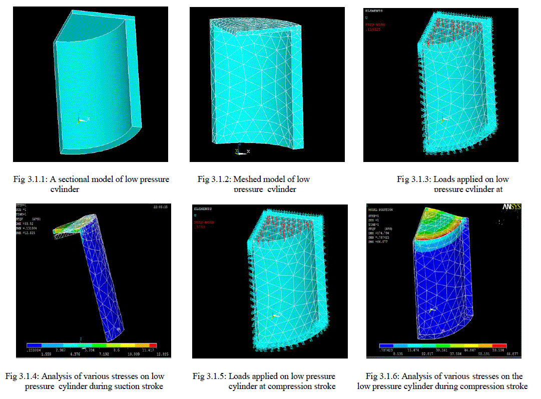
| Fig 3.1.1 is sectional model of low pressure cylinder under study, designed for given specification as mentioned above. Fig 3.1.2 Shows model is meshed with 10 nodded tetrahedral elements. There are many elements used for meshing but we had picked randomly 10 nodded tetrahedral element. For the meshed model applied pressure of 1.10325 bars on the lower part of the cylinder head inner walls of the cylinder during the suction stroke of low pressure cylinder shown in fig 3.1.3. Fig 3.1.4 shows analysis of various stresses on low pressure cylinder during suction stroke. The stress concentration is distributed on different areas and these areas are indicated by different colors. The maximum stress is indicated by red color, which is having a stress value of 12.825 N/mm². Fig 3.1.5 shows loads applied on low pressure cylinder at compression stroke a pressure of 5.753 bar is applied on the lower part of the cylinder head during the compression stroke of low pressure cylinder. Fig 3.1.6 shows analysis of various stresses on the low pressure cylinder during compression stroke. The stress concentration is distributed on different areas and these areas are indicated by different colors. The maximum stress is indicated by red color, which is having a stress value of 66.811 N/mm². |
| High Pressure Cylinder |
| Material Specification : cast iron |
| `Inner diameter of the cylinder = 55 mm |
| Outer diameter of the cylinder = 82 mm |
| Length of the cylinder = 61 mm |
| Cylinder head thickness = 5 mm |
| Young’s modulus = 100 N/mm² |
| Poisson’s ration = .211 |
 |
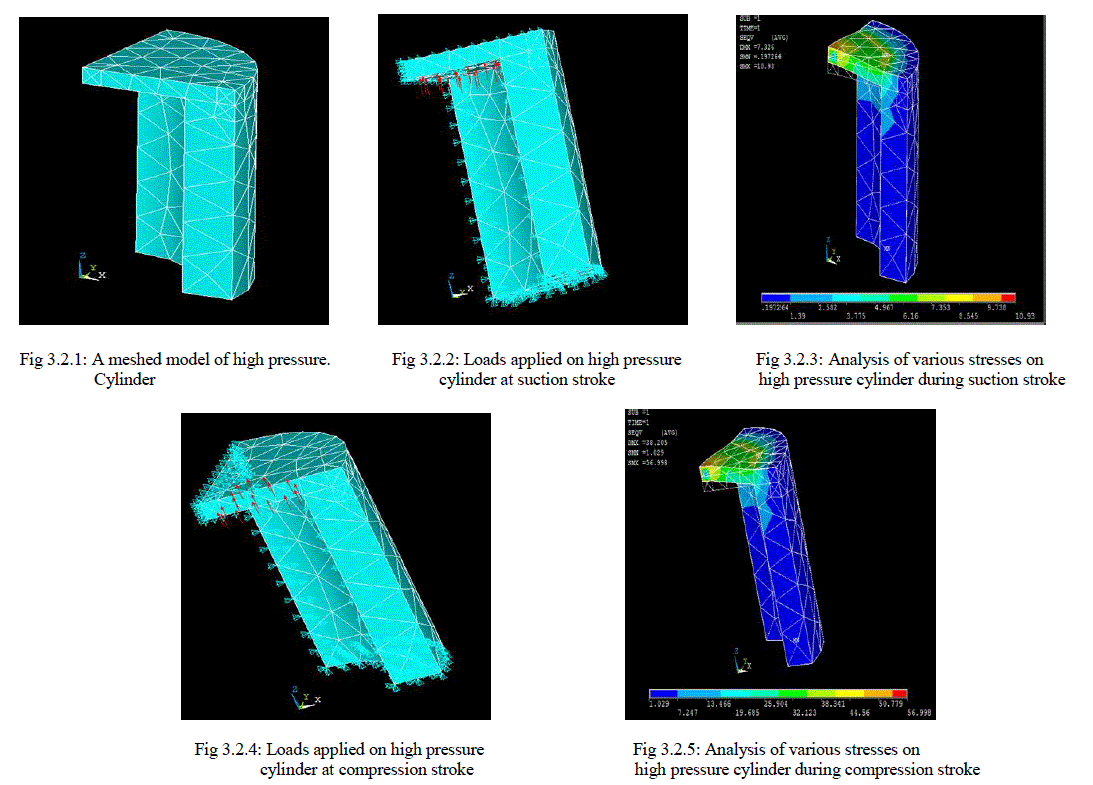
| Fig 3.2.1 shows a meshed model of high pressure cylinder. |
| Fig 3.2.2 shows loads applied on high pressure cylinder at suction stroke. A pressure of 5.753bar is applied on the lower part of the cylinder head inner walls of the cylinder during the suction stroke of high pressure cylinder. Fig 3.2.3 shows analysis of various stresses on high pressure cylinder during suction stroke. The stress concentration is distributed on different areas and these areas are indicated by different colors. The maximum stress is indicated by red color, which is having a stress value of 10.93 N/mm². Fig 3.2.4 shows loads applied on high pressure cylinder at compression stroke. A maximum pressure of 30 bar is applied on the lower part of the cylinder head during the compression stroke of high pressure cylinder. Fig 3.2.5 shows analysis of various stresses on high pressure cylinder during compression stroke. The stress concentration is distributed on different areas and these areas are indicated by different colors. The maximum stress is indicated by red color, which is having stress value of 56.998 N/mm². |
| Low Pressure Piston |
| Material Specification: Aluminum alloy 7075 T6 |
| Piston diameter = 120 mm |
| Thickness of piston head = 5.13 mm |
| Length of piston rod = 150 mm |
| Radial width of piston ring = 4.5 mm |
| Thickness of piston barrel = 13 mm |
 |
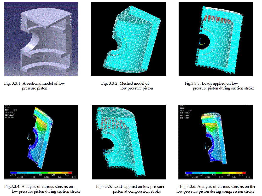
| Fig.3.3.1 shows a sectional model of low pressure piston. |
| Fig 3.3.2 shows meshed model of low pressure piston. Meshed with 10 nodded tetrahedral elements. there are many elements used for meshing but we had picked randomly 10 nodded tetrahedral element. Fig 3.3.3 shows loads applied on low pressure piston during suction stroke. A pressure of 1.10325 bars is applied on the lower part of the cylinder head inner walls of the cylinder during the suction stroke of low pressure cylinder Fig 3.3.4 shows analysis of various stresses on low pressure piston during suction stroke. The stress concentration is distributed on different areas and these areas are indicated by different colors. The maximum stress is indicated by red color, which is having a stress value of 6.908 N/mm² Fig.3.3.5 shows loads applied on low pressure piston at compression stroke. A pressure of 5.753 bars is applied on the top of the piston head during the compression stroke of low pressure piston. Fig.3.3.6 shows analysis of various stresses on the low pressure piston during compression stroke. The stress concentration is distributed on different areas and these areas are indicated by different colors. The maximum stress is indicated by red color, which is having a stress value of 6.908 N/mm². |
| High Pressure Piston |
| Material Specification: Aluminum Alloy 7075 t6 |
| Piston diameter = 55 mm |
| Thickness of piston head = 5.38 mm |
| Length of piston rod = 77 mm |
| Radial width of piston ring = 1.78 mm |
| Thickness of piston barrel = 9 mm |
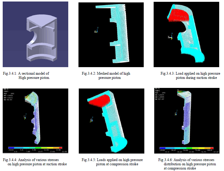 |
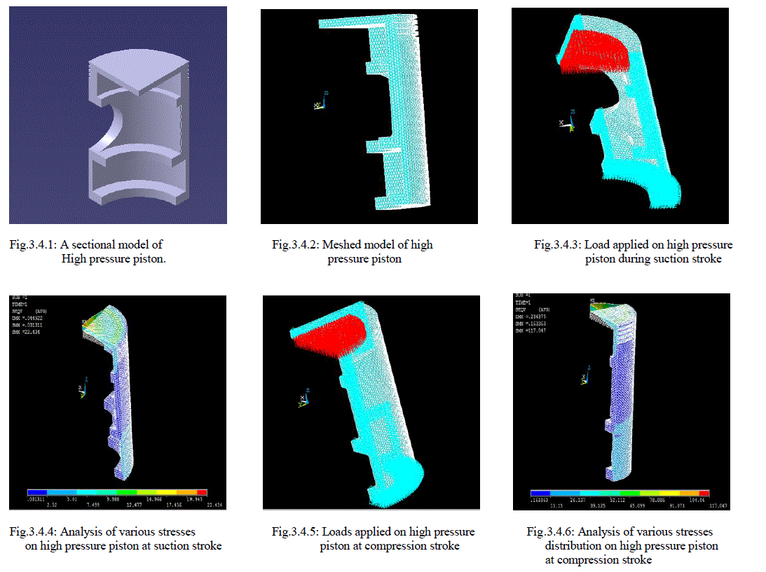
| Fig.3.4.1 shows a sectional model of low pressure piston. |
| Fig.3.4.2 shows meshed model of high pressure piston. Meshed with 10 nodded tetrahedral elements. There are many elements used for meshing but we had picked randomly 10 nodded tetrahedral element. Fig.3.4.3 shows load applied on high pressure piston during suction stroke. A pressure of 5.753 bars is applied on the top of the piston head during the suction stroke of high pressure piston. Fig.3.4.4 shows analysis of various stresses on high pressure piston at suction stroke. The stress concentration is distributed on different areas and these areas are indicated by different colors. The maximum stress is indicated by red color, which is having a stress value of 22.434 N/mm². Fig.3.4.5 shows loads applied on high pressure piston at compression stroke. A pressure of 30 bars is applied on the top of the piston head during the compression stroke of high pressure piston. Fig.3.4.6 shows analysis of various stresses distribution on high pressure piston at compression stroke. The stress concentration is distributed on different areas and these areas are indicated by different colors. The maximum stress is indicated by red color, which is having a stress value of 117.047 N/mm². |
CONCLUSION |
| FOR LOW PRESSURE CYLINDER THE MAXIMUM STRESS DURING SUCTION STROKE IS 12.825 N/MM² AND DURING COMPRESSION STROKE IS 66.877 N/MM², WHICH IS LESS THAN ALLOWABLE STRESS. SO THE DESIGN IS SAFE. THE MAXIMUM STRESS IS OBTAINED AT CYLINDER HEAD AND ALSO AT THE JOINT OF CYLINDER AND CYLINDER HEAD, AND THERE IS A POSSIBILITY OF FAILURE AT THESE AREAS. |
| 2.) For high pressure cylinder the maximum stress during section stroke is 10.93 N/mm² and during compression stroke is 56.998 N/mm², which is less than the allowable stress. So the design is safe. The maximum stress is obtained at cylinder head and also at the joint of cylinder and cylinder head, and there is a possibility of failure at these areas. |
| 3.) For low pressure piston the maximum stress during suction stroke is 6.908 N/mm², which is less than allowable stress. So the design is safe. The maximum stress is obtained at the joint of the piston crown and piston barrel, and there is a possibility of failure at these areas. |
| 4.) For high pressure piston the maximum stress during suction stroke is 22.434 N/mm² and during compression stroke is 117.047 N/mm², which is less than allowable stress. So the design is safe. The maximum stress is obtained at the joint of the piston crown and piston barrel, and there is a possibility of failure at these areas. |
| 5.) It is observed that for the cylinder the stress increases up to certain distance and remains constant from the edge of the cylinder to the cylinder head in the radial direction. 6.) It is observed that for the piston the stress decreases from the centre of the piston crown up to a certain distance and then reaches a maximum value at the joint of the piston then decreases along the piston barrel. |
FUTURE WORK |
| We dealt only with structural analysis of the cylinder and piston this work can be further extended to the analysis of connecting rod and crankshaft and also thermal analysis of these components. |
References |
|