ISSN ONLINE(2278-8875) PRINT (2320-3765)
ISSN ONLINE(2278-8875) PRINT (2320-3765)
Ms. Sulochana T1 , Mr. Dilip Chandra E2, Dr. S S Manvi3, Mr. Imran Rasheed4
|
| Related article at Pubmed, Scholar Google |
Visit for more related articles at International Journal of Advanced Research in Electrical, Electronics and Instrumentation Engineering
Image fusion is extracting the required information from the two input images. The resultant will be the complete featured images. This is done by averaging the two images. in this paper focusing on DWT with different filters are haar, biorthogonal and daubechies to measure the quality of the image .When PSNR performance is high with MSE is low ,image quality is good. The DWT filters gives the different PSNR value, by comparing the filters, daubechies filter is chosen as best. This design is analysed and tested in MATLAB SIMULINK R2012b.The model is generated using MATLAB software.
Keywords |
| Image Fusion, DWT, IDWT, PSNR, MSE. |
I.INTRODUCTION |
| Image processing is one kind of signal processing for this image acts as input, it may be either photo or video frame and the outcome of image processing may be either an image or a set of characteristics related to the image. Most of the image-processing techniques, image of two-dimensional signal is treated as input and standard signal-processing techniques are applied to it. Image and video compression is an active application area in image processing. In the field of Image processing, image fusion has received a significant attention for remote sensing, medical imaging, machine vision and the military applications. A hierarchical idea of image fusion has been proposed for combining significant information from several images into one image. |
| The aim of image fusion is to achieve improved situation assessment and/or more fast and accurate completion of a pre-defined task than would be possible using any of the sensors individually. Mainly image fusion requires precise techniques and also good understanding of input data. The final output of image fusion is expecting to provide more information than any of the single images by reducing the Mean Square Error (MSE). |
| A. Introduction to Image Fusion: |
| Image fusion is the process that combines information from multiple images of the same scene. These images may be captured from different sensors, acquired at different times, or having different spatial and spectral characteristics. The object of the image fusion is to retain the most desirable characteristics of each image. With the availability of multi sensor data in many fields, image fusion has been receiving increasing attention in the researches for a wide spectrum of applications [1]. |
| B. Discrete Wavelet Transform (DWT) technique |
| The two-dimensional DWT is becoming one of the standard tools for image fusion in image and signal processing field. The DWT process is carried out by successive lowpass and highpass filtering of the digital image or images. This process is called the Mallat algorithm or Mallat-tree decomposition. The main significance of Mallat algorithm is which connects the continuous-time multi-resolution to discrete-time filters. The idea behind image fusion using wavelets is to fuse the wavelet decompositions of the two original images by applying fusion methods to approximations coefficients and details coefficients. By observing the performance of all the image fusion techniques, the DWT gives efficient results. Due to its orthogonality, DWT technique has been chosen for compression and decompression for the FPGA implementation of the image fusion technique[2]. |
II.SYSTEM DESIGN |
| A. DWT based image fusion |
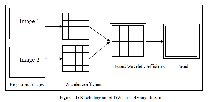
| The requirement for the successful image fusion is that images have to be correctly aligned on a pixel-by-pixel basis. In this project, the images to be combined are assumed to be already perfectly registered[1][2]. The Figure (1) shows the top level block diagram of image fusion using wavelet transform. The two input images image1and image 2 that are captured from visible and infrared camera respectively are taken as inputs. The wavelet transform decomposes the image into low-low, low-high, high-low, high-high frequency bands. The wavelet coefficients are generated by applying the wavelet transform on input images. Wavelet coefficients of the input images are fused by taking the average of input images. The resultant fused image is obtained by applying the inverse wavelet transform[3]. |
 |
| The designing and modelling of fusion of two images by averaging and 2-D DWT with different filters like Haar, Daubechies and Biorthogonal filters in MATLAB Simulink. The results of all fusion techniques for three different set of images has been carried out. The PSNR of different set of images for different fusion techniques has been tabulated. |
| B. Introduction to DWT |
| The Discrete Wavelet Transform (DWT) is frequently encountered in numerous applications involving image and video compression, pattern, recognition, bioinformatics, and so on. Due to its incredible advantage over the discrete cosine transform (DCT), 2-D DWT has been adopted for designing of image fusion technique. High PSNR and clear fused image is achieved by 2-D DWT with 9/7 Daubechies filter [2]. |
| C. Detailed block diagram of DWT based image fusion |
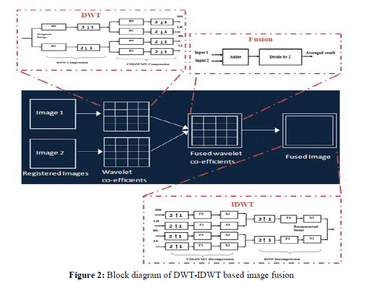
| DWT- IDWT plays a vital role in image fusion technique. In this project, the registered images have been considered for fusion process, since it is necessary that the images have to be correctly aligned on a pixel-by-pixel basis to achieve successful image fusion. DWT has been modelled at the transmitter and IDWT has been modelled at the receiver. The wavelet transforms of the images has been computed. The registered images have been passed as input signals through two different one-dimensional digital filters H0 and H1 respectively. H0and H1digital filters perform high pass and low pass filtering operations respectively for both the input images. The output of each filters are followed by sub-sampling by a factor of 2. |
| This step is referred as the Row compression and resultant is called as L-low frequency component and H-high frequency component. The down sampled outputs have been further passed to two one dimensional digital filters in order to achieve Column compression. The HH-High High, HL-High Low, LH-Low High and LL-Low Low are the output frequency components obtained after two level compressions of both the input images. The Figure 2 shows the block diagram of DWT based image fusion process which consists of two input images, DWT block, fusion block and IDWT block. |
| The HH, HL, LH and LL frequency components of one input image is fused with the HH, HL, LH and LL components of second image respectively. HH components of both images have been added and then the resultant output has been divided by a factor 2. Similarly, the average of HL, LL and LH components has been taken. This process is known as Image Fusion. This averaged result has been future followed by the reconstruction process i.e., inverse wavelet transform. |
| IDWT is the reverse process of DWT. In IDWT process, the HH, HL, LH and LL components have been first upsampled and then filtering operation has been carried out. The sub-bands has been added or summed to get the resultant reconstructed image. The DWT based image fusion technique produced the more naturally fused image even when the images to be combined have been taken from different cameras. |
 |
III. SYSTEM DESIGN USING MATLAB SIMULINK |
| A. Modelling of DWT-IDWT based image fusion |
| Wavelet-based coding is more robust under transmission and decoding errors, and also facilitates progressive transmission of images. Wavelet coding schemes are especially suitable for applications where scalability and tolerable degradation are important (Swastik 2009) |
| The designing and modelling of fusion of two images has been processed in MATLAB Simulink R2012b. In this project four different fusion approaches, Averaging and DWT with different filters like Haar, Daubechies and Biorthogonal have been developed in order to choose the best one. It is essential that all the source images used in this project have been already correctly aligned on a pixel-by-pixel basis, a prerequisite for successful image fusion. The fusion techniques have been tested with five sets of images, which represent different feasible applications where fusion can be performed. |
| The sets of images that have been used for this project may be of size ‘M X N’. The set of images consists of pictures that have been captured from different cameras, one from visible and other from infrared camera. |
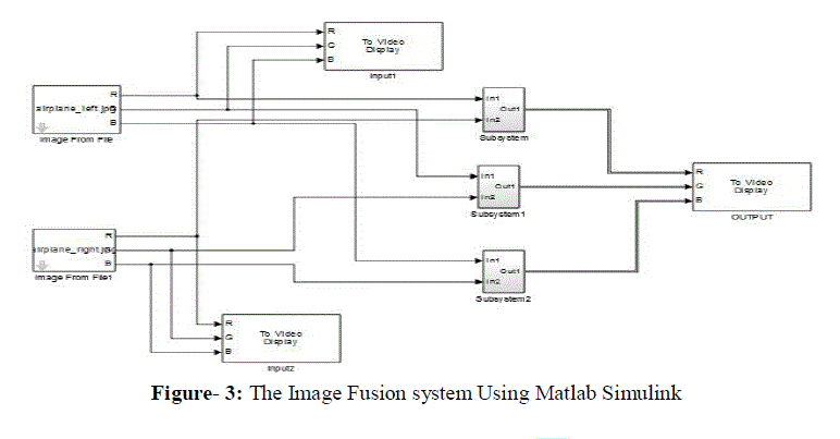
| The Figure 3 shows the developed software reference model for image fusion. The image from file block has been used to import an image from a supported image file. If the image is of M-by-N array, the block outputs a binary or intensity image, where M And N are the number of rows and columns in the image. Since the color images have been used for fusion process, it is necessary to separate the Red, Green and Blue components of image. To do so, the separate color signals option has been selected in the image from file dialog box. The fusion step has been carried out for all RGB components separately. The output has been fed to the resize block to make the input images of same size. The resize block enlarges or shrinksan image to ‘256 X 256’ by resizing the image along one dimension (row or column). Then, it resizes the image along the other dimension (column or row). Resized image has been fed to Frame Conversion Block to convert the intensity values of image to frames by selecting the Frame based output sampling mode. By selecting the sampling mode the parallel input has been converted to serial output. The serial data has been fed as inputs to the DWT block [4]. |
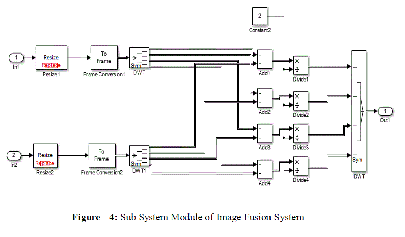
| The DWT block computes the two set of coefficients: approximation coefficients and detail coefficients. These vectors have been obtained by convolving the input values with the low-pass filter for approximation and with the high-pass filter for detail and results into a collection of sub-bands with smaller bandwidths and slower sample rates. If the length of each filter is equal to 2N i.e., n = length (input signal), then the output signals from filters are of length n + 2N − 1, and then the low pass and high pass coefficients are of length floor [{(n-1)/2}+N]. The 2-level DWT compression produces four sub-bands HH, HL, LH and LL. The sub-bands of both images are fused by combining HH coefficient of first image with HH coefficient of second. Similarly for the remaining coefficients HL have been fused with HL, LH has been fused with LH and LL has been fused with LL. Fusion has been carried out in two steps: |
| Step 1: the image coefficients have been added and |
| Step 2: the added output has been divided by a factor 2. |
| The fused output has been fed as input to the IDWT block. IDWT block has been used to compute the inverse discrete wavelet transform (IDWT) or reconstruct a signal from sub bands with smaller bandwidths and slower sample rates. When the block computes the inverse wavelet transform of the input, the output has the same dimensions as the input. Each column output is the IDWT of the corresponding input column. When reconstructing a signal, the blocks uses a series of high pass and low pass FIR filters to reconstruct the signal from the input sub-bands. The reconstructed signal has a wider bandwidth and faster sample rate when compare to the input sub-bands, this is shown in the figure (4) [6]. |
 |
 |
| Modelling of sub-blocks |
| Its represents the designing and modelling of fusion of two images by averaging and 2-D DWT with different filters like Haar, Daubechies and Biorthogonal filters in MATLAB Simulink Figure (4). |
| Averaging |
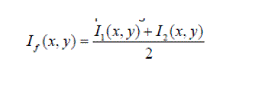
| It is the simplest method and fusion has been carried out just by taking the mean-value of xth corresponding pixels. This is a fundamental technique of image fusion. Image fusion is achieved by simple averaging corresponding pixels in each input image as follows |
 |
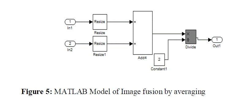 |
| The Figure (5) shows the MATLAB simulink model of image fusion by averaging. The input images of size M X N has been read from the file by image from file simulink block and has been divided into RGB components by selecting the separate colour signals option. The sample time of 10 has been specified, which gives the output signal with 10 sample period. The fusion step has been carried out for all RGB components separately. The output has been fed to the resize block to make the input images of same size. The resize block enlarges or shrinksan image to ‘256 X 256’by resizing the image along one dimension (row or column). Then, it resizes the image along the other dimension (column or row). The resized output has been fed to the adder, then dividing by the factor 2 and the resultant is the fused image. |
IV: EXPERIMENTAL RESULTS |
 |
 |
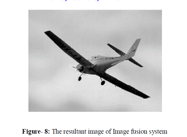 |
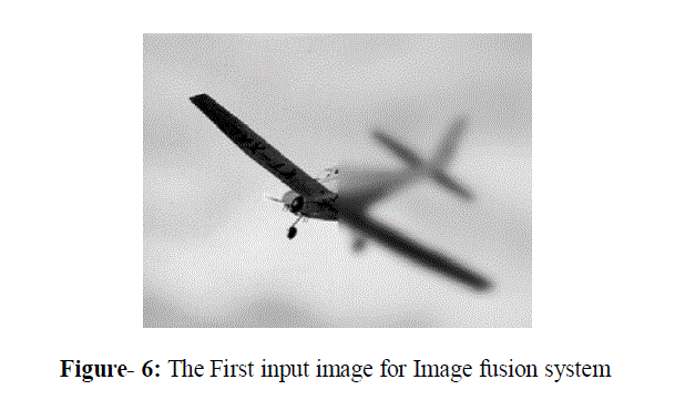
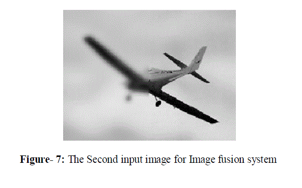
| The figure (6) and (7) are the inputs of the image fusion system. These images have half of the image is blur and half of image is good. The resultant output of the image fusion system is as shown in figure (8) it is reconstructed by using input images. The output depends on the window which is used in the DWT and IDWT. In this model the Daubechies filter is used because it provides good output as compared to other filters. |
V. CONCLUSION |
| Analysis was carried out to choose the type of image fusion technique that should has the property of orthogonality and should results in less MSE and high PSNR. Daubechies 9/7 is selected for the designing of project since it is the above features to produce appropriate result by referring to the IEEE journals, books and manuals. The software reference model of the chosen architecture is developed in Matlab Simulink R2012b. The DWT outputs of two input images are fused and the resultant fused image is passed to IDWT to reconstruct the original size of the image. The resultant fused image should contain the information or data from both the input images. The software reference model is verified by calculating the MSE and PSNR values. By observing the PSNR values of different types of fusion techniques like averaging and 2-D DWT with different filters like haar, daubechies and biorthogonal, it is stated that daubechies 9/7 results in higher PSNR vales. |
ACKNOWLEDGEMENT |
| My sincere thanks to my guides Asst Prof Dilip Chandra E,Department of E&C, RITM, Bangalore Dr.Sunil kumar s Manvi HOD Dept of ECE RITM Bangalore and Prof. Imran Rasheed, Asst Prof Dept of EEE, MSRSAS Bangalore for their guidance, constant encouragement and wholehearted support. |
References |
|