ISSN ONLINE(2319-8753)PRINT(2347-6710)
ISSN ONLINE(2319-8753)PRINT(2347-6710)
Shinde Nikhil1, Vishwakarma Prem1, Sanjay Kumar1, Godse Rahul1, P.A. Patil2
|
| Related article at Pubmed, Scholar Google |
Visit for more related articles at International Journal of Innovative Research in Science, Engineering and Technology
The growth of Indian manufacturing sector depends largely on its productivity & quality. Productivity depends upon many factors, one of the major factors being manufacturing efficiency with which the operation /activities are carried out in the organization. Productivity can be improved by reducing the total machining time, combining the operations etc. In case of mass production where variety of jobs is less and quantity to be produced is huge, it is very essential to produce the job at a faster rate. This is not possible if we carry out the production by using general purpose machines. The best way to improve the production rate (productivity) alongwith quality is by use of special purpose machine. Usefulness and performance of the existing radial drilling machine will be increased by designing and development of twin spindle drilling head attachment. Human force is required to drill the hole, drilling depth cannot be estimated properly, job may spoil due to human errors, and different size holes cannot be drilled without changing the drill bit. Consumes lot of time for doing repeated multiple jobs, these all are the drawbacks. To overcome all these problems, this automated drilling machine is designed which is aimed to drill the holes automatically over a job according to the drilling depth. The main concept of this machine is to drill the holes over particular jobs repeatedly at different depths, sequence is maintained. As the machine contains drill motor, the movement is controlled accurately. This paper deals with such development undertaken for similar job under consideration alongwith industrial case study
Keywords |
| Various methods, working of twinspindle drilling machine, Design, Manufacturing. |
INTRODUCTION |
| Twin-spindle drilling machines are used for mass production, a great time saver where many pieces of jobs having two holes are to be drilled. Twin-spindle head machines are used in mechanical industry in order to increase the productivity of machining systems. The twin spindle drilling machines is a production type of machine. It is used to drill two holes in a work piece simultaneously, in one setting. The holes are drilled on number of work pieces with the same accuracy, so as to make them interchangeable. This machine has two spindles driven by a single motor and all the spindles are fed in to the work piece simultaneously. Feeding motions are obtained either by raising the work table or by lowering the drills head. In mass production work drill jigs are used for guiding the drills in the work piece so as to achieve accurate results. |
| Drilling depth cannot be estimated properly, job may spoil due to human errors, and different size holes cannot be drilled without changing the drill bit. Consumes lot of time for doing repeated multiple jobs, these all are the drawbacks. To overcome all these problems, this automated drilling machine is designed which is aimed to drill the holes automatically over a job according to the drilling depth. The main concept of this machine is to drill the holes over particular jobs repeatedly at different depths, sequence is maintained. |
| • Method Of Multispidle |
| Fixed Multispindle drilling head |
| Where cannot change the centre distance to some range. Is planetary gear train, compound gear train. Features of both the type multispindle drilling head are |
| a. By using these twinspindle drilling heads, increase the productivity is substantial. |
| b. Time for one hole drilling is the time for multiple no. of holes drilling. |
| Conventional drilling machine carries out operations as listed below, |
| 1. Drilling |
| 2. Reaming |
| 3. Tapping |
| 4. Countersinking |
| 5. Spot facing , etc. |
PRINCIPLE OF MULTIPLE SPINDLE DRILLING |
| âÞâ As the name indicates twin spindle drilling machines have two spindles driven by a single power head, and these two spindles holding the drill bits are fed into the work piece simultaneously. |
| âÞâ The spindles are so constructed that their centre distance can be adjusted in any position within the drill head depending on the job requirement. For this purpose, the drill spindles are connected to the main drive by means of universal joints. |
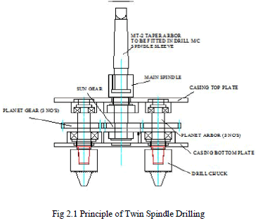 |
| âÞâ The rotation of the drills are derived from the main spindle and the central gear through a number of planetary gears in mesh with the central gear and the corresponding flexible shafts. |
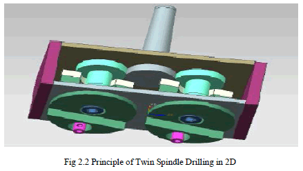
| âÞâ There are two planet gears and one sun gear arrangement for transmitting the power from main spindle to planet shaft. |
 |
DESIGN PROCEDURE |
| In our attempt to design a special purpose machine we have adopted a very a very careful approach, the total design work has been divided into two parts mainly; |
| • System design |
| • Mechanical design |
| System design mainly concerns with the various physical constraints and ergonomics, space requirements, arrangement of various components on the main frame of machine no of controls position of these controls ease of maintenance scope of further improvement; height of m/c from ground etc. In Mechanical design the components are categoriesed in two parts. |
| • Design parts |
| • Parts to be purchased. |
| For design parts detail design is done and dimensions thus obtained are compared to next highest dimension which are readily available in market this simplifies the assembly as well as post production servicing work. The various tolerances on work pieces are specified in the manufacturing drawings. The process charts are prepared & passed on to the manufacturing stage .The parts are to be purchased directly are specified &selected from standard catalogues. In system design we mainly concentrate on the following parameter such as System selection based on physical constraints, Arrangement of various components, Components of system, Chances of failure, Servicing facility, Height of m/c from ground, Weight of machine. |
| 3.1Motor Selection |
| Motor : single Phase AC motor |
| Power: 440 watt |
| Speed : 2800 rpm |
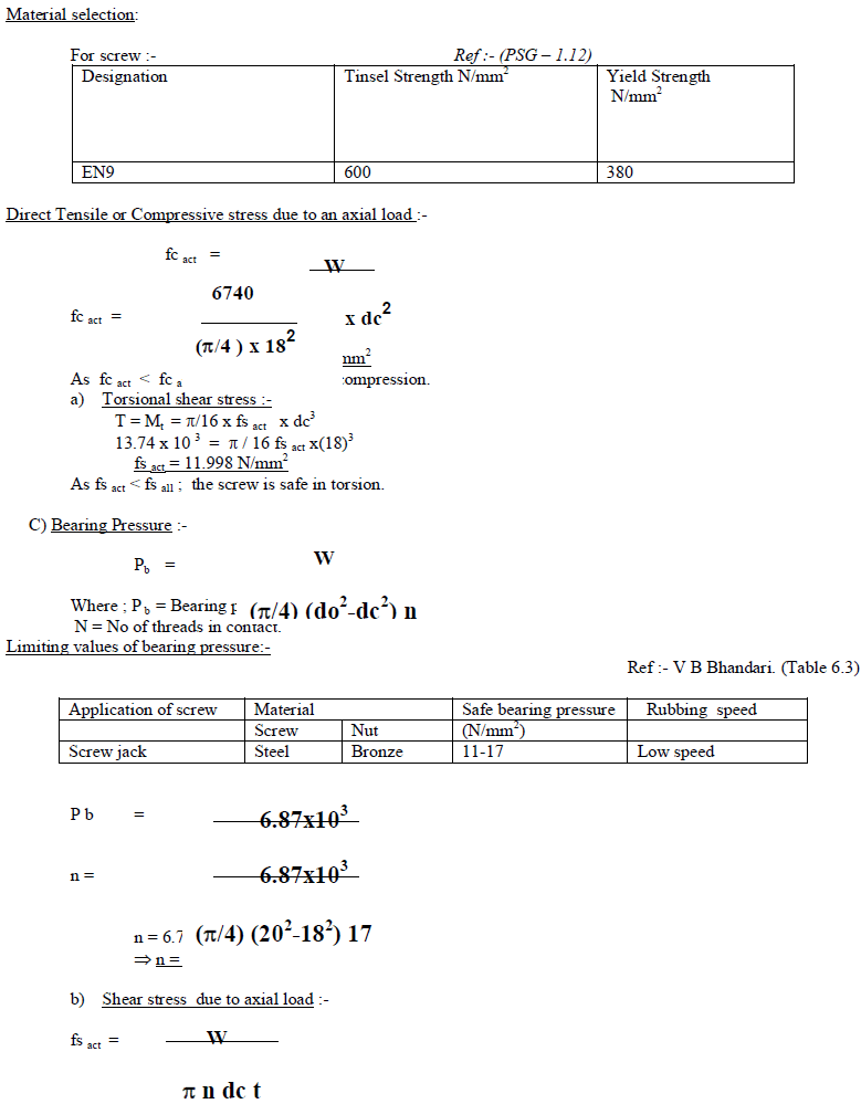
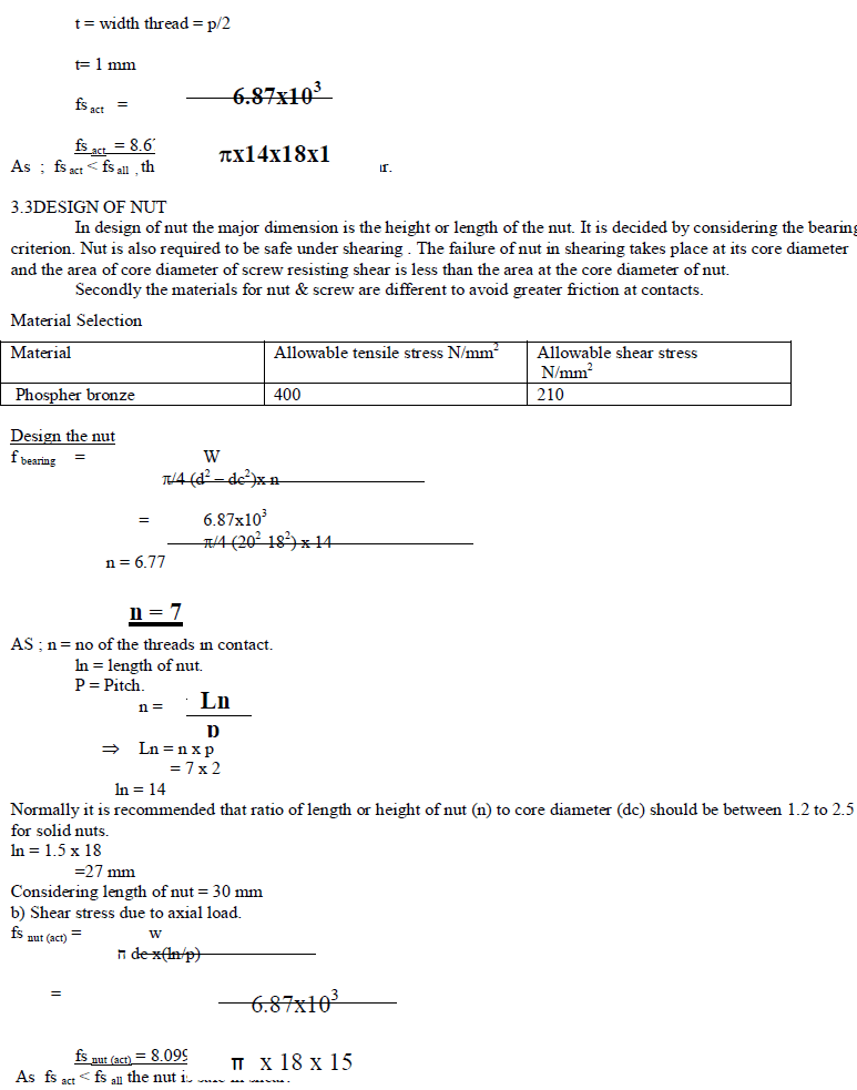
| 3.2Power Screw |
| MOTOR SPECIFICATIONS |
| TORQUE 3.5kg- cm at 1440 rpm |
| T= 0.035 kg-m =0.358 N-m at 1440 rpm |
| Assuming an transmission ratio of 1:40 between motor and the screw using gear box |
| Tdesign = 40 X 0.358 = 13.74 N-m |
| The total external torque applied to handle is 13.74 N-m |
| Therefore, |
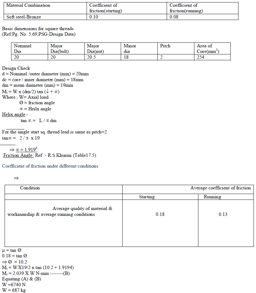
| (Mt) = 13.74 N-m---------(A) |
| ïÃÆÞ W X T = 13.74 N-m |
| Where ; T = (dm/2) tan (ïÃâï + ïÃâõ) |
| Initially assuming dimensions of screw , which we shall check under the given system of forces. |
| Selecting material combination for screw and nut |
| (Ref:Pg. No. 170,Design of Machine elements ,V B Bhandari) |
 |
 |
 |
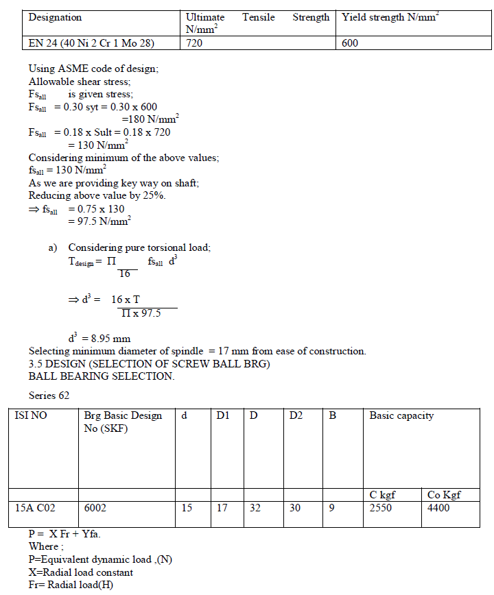
| 3.4 DESIGN OF WORM WHEEL SHAFT. |
| TDesign = 13.74 Nm. |
| = 13.74 x 10³ N.mm |
| Selection of material |
| Ref : - PSG Design Data. |
| Pg No: - 1.10 & 1.12.,1.17 |
 |
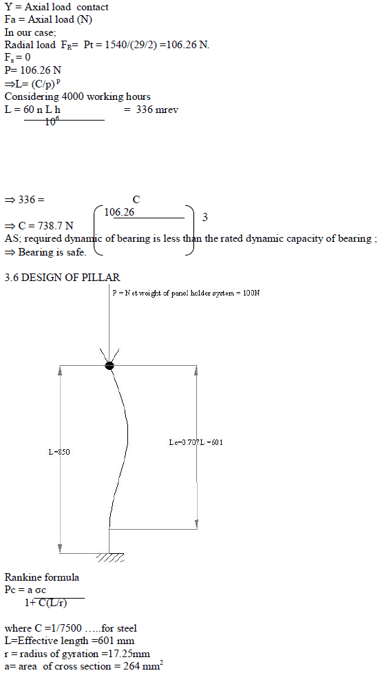 |
| Selection of boom material |
| Ref :- PSG Design Data. |
| Pg No :- 1.11 |
 |
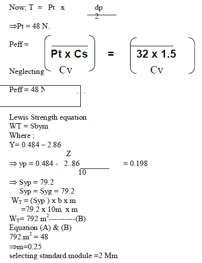
| 3.7DESIGN OF SPUR GEAR PAIR GEARED MOTOR AND SCREW |
| Power = 01/15 HP = 50 watt |
| Speed = 1000 rpm |
| b = 10 m |
| Tdesign = 0.48 N.m |
| Sult pinion = Sult gear = 400 N/mm2 |
| Service factor (Cs) = 1.5 |
| dp = 20 |
| T = T design = 0.48 N-m |
 |
| This modul e is selected with the view that the proper mesh between sun –planet-and ring gear is done |
| GEAR DATA |
| No. of teeth on sun=10 |
| No. of teeth on planet gear =22 |
| Module = 2mm |
NOMENCLATURE |
| dp = Diametral pitch |
| m =Module |
| Td= Tensional Shear Failure of Shaft |
| Tdesign= Torsional load |
| fs act = Actual shear stress |
| fs max = Max. shear stress |
| fs all =Allowable shear stress |
| d = Minimum diameter of input shaft |
| Sult= Ultimate tensile strength |
| Sylt = Yield tensile strength |
| Cs =Service factor |
| Cv =Velocity Factor |
| Pt=Tangential load |
| b =Face width (mm) |
| dp= Pitch circle diameter |
| Peff= Effective load |
| WT =Lewis Strength |
| Y = Lewis Form Factor |
| Z=Number of teeth P= Power |
CONSTRUCTION |
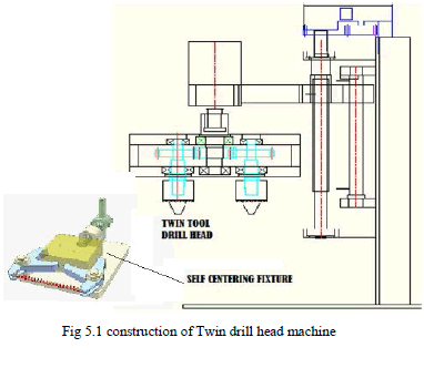
| The twin-spindle drilling attachment is mounted on the drilling machine spindle sleeve, for extra stability an support sleeve may be mounted. The cutting tools as per the job requirements are mounted in the respective three drill chucks of the drilling attachment. |
 |
WORKING |
| When machine is started the drilling machine spindle sleeve drives the arbor and thereby the planet gear system and the drill chucks and respective cutting tools, when the drilling machine spindle is fed in the downward direction the cutting action takes place. For enhancement and fast production an indexable drill jig can be mounted on the drill machine table. |
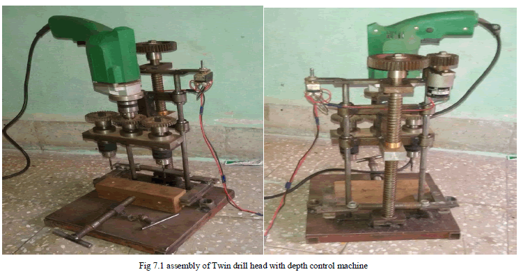
| The mechanical transmission section is controlled with stepper motor, based on the drilling depth; the switch restricts the movements of drill motor through stepper motor. Entire process falls under the subject of Mechanics, & various fields of technologies must be included to full-fill the target. The integration of electronic engineering, mechanical engineering, electrical engineering, & control technology is forming a crucial part in this design. Especially the control circuit designed with microcontroller plays dominant roll in this project work. The method of converting rotary to linear motion is implemented in the mechanism. The power screw is designed which operates a stepper motor according to the switch. |
ASSEMBLY |
| Drilling is nothing but the use of a rotating multi-point drill to cut a round hole into a work piece. In a lot of manufacturing processes, one of the most indispensable machining tools is the multiple spindle drilling machine. The drilling machine is commonly called a drill press and is responsible for drilling various sizes of holes in any surface area and to precise depths. Aside from the fact the drilling machine is used primarily in drilling holes, there are a few other functions that the multiple spindle drilling machine is capable of performing. These functions include tapping, spot facing, reaming, countersinking, and counter boring to name a few. |
 |
CONCLUSION |
| âÞâ With the help of this machine we can drill two holes at a time. |
| âÞâ Desired depth of the hole can be obtained |
| âÞâ The size of machine is smaller than the older machine so it is very simple to move from one place to another. So this machine can be easily transported. The overall space required is also minimum. |
| âÞâ The efficiency of this machine is better than the older machine. |
| âÞâ Large saving in power have been achieved. |
| âÞâ The machine is very simple to operate. |
| âÞâ No need of skilled operator for the operation. |
| âÞâ Power feed technology is implemented such that human efforts are not required for applying the force during drilling. Stepper motor is used to pull down the drilling machine while drilling. |
| âÞâ In this concept the vertical movement of the drilling machine will be restricted automatically. |
References |
|