ISSN ONLINE(2319-8753)PRINT(2347-6710)
ISSN ONLINE(2319-8753)PRINT(2347-6710)
H.P. Masebu1,D. R. White2, L. Chico-Santamarta3,M. J.Crook2, R.J. Godwin4
|
| Related article at Pubmed, Scholar Google |
Visit for more related articles at International Journal of Innovative Research in Science, Engineering and Technology
Cereals like sorghum, maize, wheat, barley and rice are the most important sources of food forbillions of people globally. They are consumed in different forms such as porridge, bread, and rice and used in various beverages. Conventional harvesters used to harvest these grains cut and feed a lot of straw together with grain into the threshing machine. However a more recent method strips grain rich material with a reduced amount of materials other than grain (MOG). A laboratory stripper rig designed for this studyconsists of three major components; a mounted stripper drum with attached stripping tools, a sample feeding mechanism, and the source of power and its controls. With this device laboratory stripping tests of cereal grains can be performed safely.
Keywords |
| Sorghum grain,stripper harvesting losses, laboratory rig |
INTRODUCTION |
| The need to improve crop production output can be fulfilled by the use of efficient machinery. However, in some parts of the world there are no suitable machines for use in agricultural production in terms of affordability and technological accessibility. This problem is common in many developing countries including Botswana which is a landlocked country in southern Africa sharing itsborders with Zimbabwe, South Africa and Namibia. Approximately eighty per cent of Botswana’s land surface area of 582,000 km2is the Kgalagadi desert dominated by deep sandy soils and with only 29,100 km2 (2.91 million ha) (5% of land area) classified as suitable for cultivation [1].Less than 6,000 km2 (600,000 ha) of the land suitable for cultivation is under cultivation. Crop production in Botswana is hindered by limited precipitationsand poor soils and therefore thereis a need to develop technology to increase food production.One of the new technologies thathavepotential for improving cereal harvesting efficiency is the stripper harvester with its grain stripping devices.The use of grain-stripping devices is becoming popular as it offers a number of benefits including reduced material other than grain (MOG) intake of up to 20% compared to cutter-bar fitted harvesters[2]. This reduction in MOG leads to reduced loading on the threshing systems and this can reduce fuel consumptionby as much as 37% to 42% [2].Reduction in the quantity of MOG intake when using the stripper header improves separation efficiency [3]allowing the separation system to handle larger quantities of the crop and increase harvesting rates when compared with the conventional cutter-bar. |
| The use of a stripper header has been found to increase combine throughput capacity by as much as 50% to 100%[4].A combine harvester fitted with a stripper header and operating at a ground speed of 7 kmhr−1was found to have similar losses to a combine fitted with conventional cutter bar with a working speed of 1.3 – 4.4 km hr−1[5] when harvesting wheat. The stripper header, therefore, had more than double the throughput of a combiner fitted with a conventional header. Observations made by Sherlbourne-Reynolds customers in the year 2010 revealed that the use of a 8.5mwide stripper header to harvest wheat resulted in throughput of as much as 27.2 tonnes hr−1, while the use of a 9.1mwide conventional header had a lower output of 19.1 tonnes hr−1[6]. The main aim of this research was to design a laboratory rig to be used in testing effectiveness of the redesigned stripping tools in stripping sorghum grain from the panicles.The specific objectives of designing and fabricating of this rig were (1)to evaluate the performance of three different (redesigned larger) stripping tools on stripping sorghum and wheat grain from the grain-bearing panicles as compared to the current commerciallyavailable smaller stripping tools, (2) investigate the effectiveness of stripping sorghum with stripper-drum rotational speeds of 120 to 500 rpm,(3) evaluate the effect of variable advance angles on stripping sorghum grain off the panicles and (4) evaluate the effect of manipulating airflow from below and into the front of the stripper-drum on reducing stripped material losses using an undercover sheet. |
MATERIALS AND METHODS |
| As a consequence of the none existence of a machine that could be adapted to stripping grain off the grain panicles, a laboratory test rig was designed and builtduring 2010/2011 in the Department of Agricultural Engineering at Harper Adams University(HAU)(Newport, United Kingdom). The indoor laboratory rig enables testing throughout the year even during adverse weather conditions in the field. Due to unfavourable growing conditions for sorghum, the crop was grown in a controlled conditions glasshouse and was subsequently harvested using the above mention stripping machine. |
| A. TEST RIG DESIGN: |
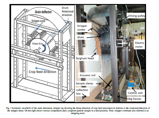
| The grain-stripping rig was designed to evaluate the capability of redesignedstripping toolsto strip sorghum grain as it is successfully used in strip harvesting of other cereals. The main components of the test rig illustrated in Fig. 1include a rotating drum mounted on a centre axle. A set of eight steel brackets are welded on the drum each of which has four 9mm diameter holes for mounting various interchangeable sets of stripping tools. The set of eight stripping tools are radially mounted on the drum periphery using M6 bolts and nuts through the matching holes on the steel brackets welded on the drum surface at a uniform spacing radial angle of 45° around the stripper drum hence eight rows of stripping tools. The steel brackets were formed into a 15° advance angle in the direction of the drum rotation as per the current commercial/conventional design. To achieve advance angles of 30°, 45°, 60° and 75° wooden wedges with angled edges of 15°, 30°, 45° and 60°, respectively were inserted between the bracket angled at 15° and the stripper finger to achieve the desired angle. The width of 300 mm was large enough to strip a single head of sorghum which is about 100 mm wide. The drum and the steel brackets were made from a sheet of 3 mm-thick mild steel sheet (EN 10130). |
 |
| B. STRIPPING TOOLS |
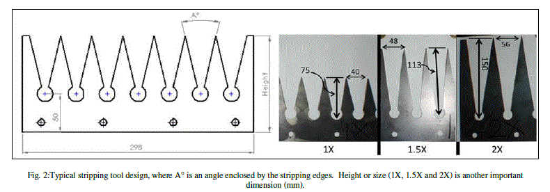
| Three stripping toolsof different sizes were designed and fabricated to evaluate the effect of varying the size and geometry of stripping tools. The original (1X*30deg) design (Table1and Fig. 2) is based on the current stripping tool used to harvest cereals commercially in USA and Europe. The coding 1X means the current size scale by unit (1) scale factor while 30deg means 30° angle enclosed between V-shaped stripping edges. To modify the current stripping tool design, two step-up scale factors of 1:1.5 (1.5X) and 1:2 (2X) were used to scale up from the original size by 50 and 100% respectively, whilst two angles of 20 and 30° enclosed by V-stripping edges were used in combination with the scale factors above. The stepping up of the current smaller original design to larger new designs was based on the fact that sorghum has larger panicles with a mean length of 269mm[7]compared to the relatively smaller wheat panicle. Comparison with wheat was due to the fact that wheat is one of the many crops harvested using stripper harvesters. It therefore, could be difficult for larger sorghum panicles to slot into the smaller original stripping tools with narrower front gaps and shorter stripping edges which are effective at stripping wheat; hence, the 1X may not be as effective on larger sorghum panicles. With these observations it was necessary to design larger stripping tools for trials on sorghum. The combination of size scale factors and angles yielded three new larger designs; 1.5X*20deg, 2X*20deg and 2X*30deg (Table1, and Fig. 2). These four (i.e. 1X*30deg, 1.5X*20deg, 1.5X*30deg and 2X*20deg) designs were evaluated for their ability to strip the grain off the sorghum and wheat panicles. These sets of stripping toolsare interchangeable on the stripper drum, where they are bolted to the stripper brackets. |
 |
| C. SAMPLEHANDLING AND PROCESSING |
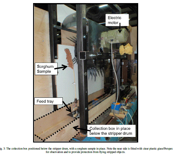
| A pneumatic actuator from Wrekin Pneumatics (serial number: KD 200-050-1600) with a linear telescopic extension of 1600mm was used to safely feed the samples into the path of the stripping toolsfitted in the rotating drum. The pneumatic actuator located 650 mm beneath the axial centre of the stripping drum is shown in Fig. 1 and Fig. 3. This arrangement was made so as to create sufficient clearance between the pneumatic actuator and the stripper drum to allow vertically mounted samples to be stripped. The pneumatic actuator positioning results in the minimum possible space of 200 mm between the highest point of the sample clamping device and the lowest point of the largest (2X) stripping tool when mounted. A directional control pneumatic valve was used to control the extension and retraction of the pneumatic actuator attached to the sample gripper mechanism.A box was positioned below the stripper drum for collection of the stripped material whilst a grain deflector was placed on top of the frame rig to deflect the grain into the collection box below the rig(Fig. 3).Perspex and plywood boards (Fig. 3) were fixed on the side frame of the rig to provide protection against flying objects. |
 |
| Fig. 3: The collection box positioned below the stripper drum, with a sorghum sample in place. Note the near side is fitted with clear plastic glass/Perspex for observation and to provide protection from flying stripped objects. |
| D. STRIPPING OF GRAIN PANICLES |
| For testing in this rig, cereal panicles onpeduncles of at least 330mm in lengthwereused(Fig. 4). The minimum limit of 330 mm height was to ensure that the whole panicle was in the path of the stripping tools. |
 |
| Before stripping, the panicles attached to the stalk were weighed and the masses were recorded to a precision of 0.1 g. The weighed samples were attached in a vertical position to the tray by a clamping mechanism made from a modified drill chuck. The modification of the drill chuck was such that it could be mounted in the sample tray. The sample tray was attached to the front of the pneumatic actuator. Care was taken to avoid weakening the sample stem during clamping which could have resulted in the sample easily bending or breaking during the process of stripping. The sample to be stripped was safely introduced into the rotating stripper drum by use of a feed tray attached to the pneumatic actuator (Fig. 3). The sample was fed into the rotating drum fitted with stripping toolsuntil it passed below and behind it, an action similar to a combine harvester advancing towards a standing crop,stripping the grain off the head of a standing crop and driving over a stripped, yet still upright, straw. At the end of the stripping process, the pneumatic actuator was stopped when it reached full extension beyond the rotating drum, after which the power to the rotating stripper drum was turnedoff. To access the stripped sample, sufficient delay was necessary to ensure that the spinning drum came to a complete stop and only then was it safe to open the safety doors and remove the stripped panicles. The relationship between the movements of the rotating stripper drum and the linear motion of the sample being fed were as follows; if the sample was positioned infront of the observer and its linear movement was horizontal from right to left then the drum being viewed would have an anticlockwise rotational movement as inFig. 1. |
| E. SOURCE OF POWER |
| The stripping drum was powered by a 0.75 kW electric motor (Fig. 3(Brown Pastell,model number SK20-80L/4). The control unit used with this electric motor was made byIMO Precision Control Ltd (type CUB8A-1). The control unit and the motor were powered by a single phase mains supply of 240 volts and the power transfer from the motor to the drum was achieved through a pair of pulleys and a timing belt. The step-up speed ratio between the driving pulley and the driven pulley used was 1:6 whilst the drum achieved a variable speed range of 120 to 550 rpm; this speed was limited due to the rotational speed of the motor and the belt and pulley system used. For these studies, the speeds used varied from 200 to 500 rpm, with 100 rpmintervals, thus covering the entire rotational speed range of the stripper drum for later experiments. |
| A digital tachometer AirflowTM TA4 anemometer was used to determine the rotational speed of the drum in rpm (resolution of 1rpm). |
| F. SAFETY |
| The stripper rig consisted of high speed moving steel components, which can be dangerous to operators and people in the vicinity of the working machine. The moving parts that needed to be covered included the drum and its attachments, driver and driven pulleys and the power transferring belts. The stripped crop parts can also form dangerous flying objects. To contain all these, a thick plywood and Perspex encasement was put around the machine, while the belts and the pulleys were covered by a metal sheet. The use of Perspex was needed if viewing was needed.To further enhance safety the operational stripper rig was firmly bolted down to a very firm base to avoid vibration when operational. Thorough assessment with the help an experienced safety officer/practitioner is recommended when using the designed stripper rig |
RESULTS AND DISCUSSION |
| This stripper rig design was successfully fabricated (Fig. 1 and Fig. 3) and usedto carry out different experiments of stripping sorghum and wheat grain panicles. |
CONCLUSION |
| The stripper rig can be used to test and carry various tests on the operation of the grain stripping mechanisms.The rotational speed of the drum range was 200 – 500rpm, however to achieve higher speed balancing the drum is recommended. The three set of redesigned interchangeable stripping tools were successfully mounted and operated. Wooden wedges were successfully used to achieve the various advance angles desired for the tests. The sample feeding pneumatic mechanism was tested and performed as required. Encasement plywood boards and Perspex is a very important safety measure to avoid injuries from flying objects. |
References |
|