ISSN ONLINE(2319-8753)PRINT(2347-6710)
ISSN ONLINE(2319-8753)PRINT(2347-6710)
Md Salman Khan1, Dr. Mir Safiulla2
|
| Related article at Pubmed, Scholar Google |
Visit for more related articles at International Journal of Innovative Research in Science, Engineering and Technology
Velocity of projectiles plays an important role in determining the response and behaviour of a target under impact. In this project metallic canister with a soft projectile, which is one of the critical dynamic components, is used to launch bird/ice pellet, to study its influence on the behaviour of aircraft and aero-engine parts. This is done by using conventional compressed air launcher which launches the projectile velocities up to 200 m/s. The canisters which house the test projectile collapse against canister arrester located at the delivery end of the launcher. The collapse characteristics of the canisters are dependent on the geometry of the tip of the arresters, material of the canisters, the shape of the canisters and the heat treatment process adapted for canisters. The impact load of the canister on the arrester can be up to several tonnes axially. This force is a function of the collapsibility of the canister at impact and in turn it is determined by the operating pressure of the launcher. It is therefore necessary to develop a velocity measuring system, which determines the dynamic axial loads on the launcher as well as the target plate, which in turn helps in studying the collapsibility parameter of the canister itself. In order to measure the high velocity of the projectile three measuring devices, namely, optical laser sensor, based on programmable logic device, copper wire and graphite rod based devices are developed and used. To provide adequate redundancy for the complex, highly dynamic and costly impact tests, two of these three velocity measuring devices are used simultaneously: (1) copper wire based sensing system and (2) graphite rod based sensing system. The measuring device input parameter is fabricated on a gun barrel with acrylic fixture at two positions at a distance of 1 m before the arrester where the canister strikes and collapses. At initial and final position, optical transmitter and receiver give the delay time when the canister passes through it by obstructing the sensing signal path. The copper wire circuit based device gives open circuit delay between the two points when canister breaks it. The time taken to travel 1m distance by the canister in the gun barrel is obtained from the device and the velocity of the canister or projectile is experimentally evaluated.
Keywords |
| Velocity, Impact, Measuring devices, Canister, Gun Barrel. |
I. INTRODUCTION |
| A measuring instrument is a device for measuring a physical quantity. In the physical sciences, quality assurance and engineering measurement are the activity of obtaining and comparing physical quantities of real world objects and events. Established standard objects and events are used as units, and the process of measurement gives a number relating the item under study and the referenced unit of measurement. Measuring instruments, and formal test methods which define the instrument's use, are the means by which these relations of numbers are obtained. All measuring instruments are subject to varying degrees of instrument error and measurement uncertainty. Scientists, engineers and other humans use a vast range of instruments to perform their measurements. These instruments may range from simple objects such as rulers and stopwatches to electron microscopes and particle accelerators. Virtual instrumentation is widely used in the development of modern measuring instruments. |
| Fundamentally, velocity relates position or distance and time. The position of the projectile relative to the target is crucial, hence the relevance of position. Time is always crucial in dynamic events, so there is a possibility that the timing (or the rate of change) of the position of the projectile is crucial meaning in velocity. Without the concept of velocity, there could be no impact. For any impact condition varying the impact velocity must be one of the main ways to affect change in terms of the response of the target, as well as the extent that response, for any subsequent damage. Velocity is an important parameter in determining the response and behaviour of a target under impact. In this project metallic canister with a soft projectile, which is one of the critical dynamic components, is used to launch bird/ice pellet, to study its influence on the behaviour of aircraft and aero-engine parts. This is done by using conventional compressed air launcher setup. Canister is basically a deep drawn cylindrical vessel, closed at the back end and open at the front end. It is the most critical Dynamic-component in a bird launcher, which accelerates the bird or ice-pellet from rest to the desired launch velocity within a few milliseconds which is measured by high velocity measuring devices. It keeps the bird/bird specimen centralized and coaxial with the launch barrel and provides necessary damping for withstanding the shock of launch impact with the arrestor lip, prevents the bird specimen from rubbing with the internal surface of the gun barrel. The canister is also expected to fold over at least partially in the circumferential direction and thus serve to seal the high pressure air at the end of the gun barrel and prevent compressed air from gushing out into the target area and introduce secondary damage and minimize obscure visibility of the target components. Extensive structural damage, many times leading to catastrophic or fatal damage to the systems., takes place in micro or mili-second time intervals, when these foreign objects collide with aircraft including aero engine. Very extensive “Certification Tests”, are therefore carried out on actual aero engine to simulate this phenomenon and make the aero engine structurally and aerodynamically as robust as needed, to meet the safety and operational requirements, within the environmental conditions in which they are expected to operate. Since these tests are very expensive and time consuming, several “Components Tests”, in test rigs are carried out, under simulated flight conditions. In either case of engine testing or testing their sub-system, compressed air bird launchers are used to hurl bird specimen or ice pellets, of known dimensions & weight, on to the target engine-parts, at a desired velocity. |
| Typical bird launcher is normally operated up to Sonic-velocity, using compressed air as the medium for accelerating the bird-specimen or ice-pellets. The main function of stainless steel canister is to centralize the ice pellet encased in a soft damping polystyrene material, such as thermocole or a foam material. The canister also prevents severe aerodynamic forces and external inertia forces from deforming the soft gelatin bird model in its accelerated flight from rest to near sonic velocity in a few milliseconds .The other major function of the canister is to get decelerated to rest in a fraction distance, collapse or fold over, and seal the gun from releasing compressed air into the test system. The canister is a thin walled cylinder with either a flat back surface or a dome-shaped semi-hemispherical back end, with the front end being open, for inserting the sabot and the bird specimen. |
| The thickness of the cylindrical body as well as that of the back end could either be uniform or variable. The wall thickness at the front end and the rear end of the canister, wall thickness over on the cylindrical body are controlled during the deep drawing process. The strength of this canister, to withstand the “Impact and Shock”, is imparted to the canister during the heat treatment process. |
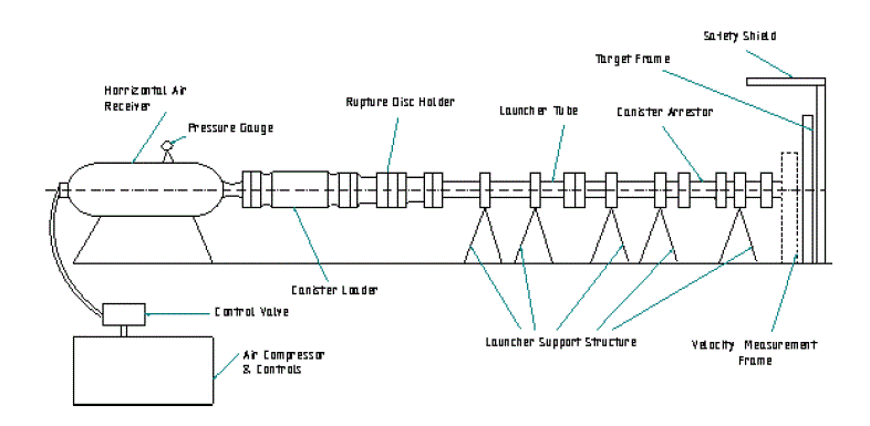
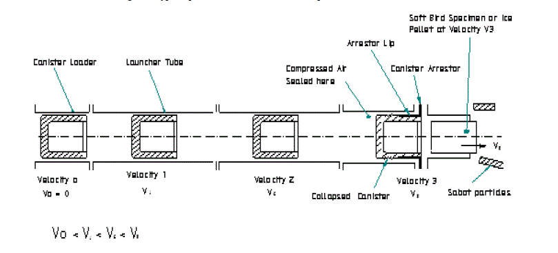
| The figure1.1 given below shows the schematic details of conventional compressed air canister launcher setup and the figure 1.2 shows the velocity of canister at different position in the gun barrel of the launcher. |
| Compressed air is used to launch the ice pellets/bird specimen or any other projectile in this facility. A metallic canister is used to hold these ice pellets and is surrounded by a layer of gelatine. A high pressure air-tank, with 1500 litre capacity 10 bar operating pressure rating, is filled with compressed air by a 10-kW air-compressor. This stored compressed air is made to suddenly gush out by opening an electronically operated solenoid valve or a sophisticated rupture disc. The expanding compressed air accelerates the ice-pellets housed in the metallic canister. The “fired” canister would accelerate throughout the length of the gun barrel/launcher tube connected to front of the air receiver, gets arrested at the Canister Arrester junction at the end of the gun barrel and ejects the ice pellets/bird specimen at the desired speed. Before the arresting action of the canister the velocity of the projectile inside the gun-barrel would be measured using a laser, copper wire and graphite rod operated velocity measuring system. |
 |
 |
| Paper is organized as follows. Section II describes literature survey on velocity measurement. The objective and goal of the project work is to measure time and velocity of the canister using optical sensor of laser type, copper wire and graphite rod as an input to the measuring devices. Scope of present work, problem statement, requirement of project and specification is given in Section III. Section IV presents methodology, Section V presents results and discussion. Section VI presents conclusion and scope of future work. |
II. LITERATURE SURVEY |
| Tanabe et al gave no definition or indication of what was meant by “high velocity” [1, 2]. Mo st mentioned “ballistic impact” but without any definition of this term. Some mentioned various events that caused the impact, such as threat from broken engine parts, turbine blades, fragments from bombs, shells, mortars, and grenades |
| Palmer et al [3] used the term medium velocity and a range of test velocities from 3-325m/s. |
| Naik et al [4] defined three classification of low, high and hypervelocity. For low velocity, the definition given is “if the contact period of impactor is longer than the time period of the lowest vibrational mode”. For high velocity, the definition given is “the response of the structural element is governed by the „localâÃâ¬ÃŸ behaviour of the material in the neighbourhood of the impacted zone”. For hypervelocity, the definition given is “such that the local target materials behave like fluids and the stress induced by the impact is many times the material strength”. The definitions focus on a characteristic end results, rather than specifying any actual values of velocity. |
| Sciuva et al [5] gave no definition, but for a specific material and specimen of interest, used range of 6-7m/s and 250- 550m/s for low and high impact tests respectively. |
| Lopez-Puente et al [6] gave the following definitions “low velocity: that of a dropped tool during assembly or maintenance operations; high velocity: impact of a released blade on the engine casing or projectile impact during flight of a military aircraft; hypervelocity: space debris impacting against a spacecraft”. For their material and specimens, they gave a range of 60-520m/s for intermediate and high velocity tests, although confusingly, 60m/s was also quoted as a low velocity for the same material and specimens. |
| Oka et al [7] gave a definition for low velocity as still being valid for the range of 50-200m/s, and mentioned subsonic to hypervelocity speeds of 300-5,500m/s. |
| Olsson claims that velocity does not govern the type of response, but the ratio of projectile and target mass does. Response types are given as a response dominated by dilatational waves with very short impact times, a response dominated by flexural waves with short impact times and a QS response with long impact times. However, contrary to this, Olsson in a later paper [8] states “For sufficiently high velocities (usually more than 70m/s for carbon/epoxy laminates) the impactor/plate mass ratio is irrelevant for the response type, as penetration occurs prior to any deflection”, and also refers to other uses of velocity, such as a delaminating damage threshold velocity. |
| Work to be done |
| The objective and goal of the project work is “Design, Fabrication and Testing of High Velocity Measuring Devices Used in Bird/Ice Pellet Canister Launcher Setup” using optical sensor of laser type, copper wire and graphite rod as an input. The centre part of the project is the microcontroller and circuit with high speed on-chip oscillators to generate clocks which is used to measure time and velocity of the canister. |
III. SCOPE OF PRESENT WORK |
| 3.1 Problem Statement |
| The title of the project is “Design, Fabrication and Testing of High Velocity Measuring Devices Used in Bird/Ice Pellet Canister Launcher Setup”. This project gives an idea about the works that has been implemented, are listed as under: |
| 1. Design and simulation |
| 2. Fabrication |
| 3. Testing of high velocity measuring devices. |
| At different pressure which is released from the reservoir tank to the gun barrel setup in which canister ice pellet is loaded in the canister loader and fired. The canister moves in the gun barrel with high velocity which has to be measured before impact to the canister arrester. The velocity measuring devices inputs are fabricated at the gun barrel just before the canister arrester. At different velocities we can observe the collapsibility and characteristics of canister. |
| 3.2 Requirement of the Project |
| A velocity is considered as one of the important parameter in the canister launcher setup. The project falls in the area of velocity measurement by using optical design based on programmable logic device, mechanical, electrical and electronic circuit with copper wire and graphite rod design based devices. This work features design and fabrication of a velocity measuring of projectile launched through the gun barrel. The centre part of the project is the microcontroller requires circuit with high speed on-chip oscillators to generate clocks which is used to measure time and velocity of the canister. |
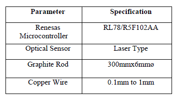
| The microcontroller used in this project is a Renesas Microcontroller which is a 30 pin microcontroller. The microcontroller features ROM 16 KB, RAM 2 KB, data flash memory 2 KB, High speed on- chip oscillator 24 MHz, On-chip single-power-supply flash memory (with prohibition of block erase/writing function), Self-programming, Onchip debug function, On-chip power-on-reset (POR) circuit and voltage detector (LVD). |
| Measuring device specification: |
 |
| 3.3 Discussion about velocity measuring devices |
| The information is available as regard to testing equipment in which the velocity of a solid particle (bird/ice pellet) can be calculated. The equipment is digitalized with view to record different parameter of test and send information using the microcontroller which provides the accurate result. Abundant information processing and characterization of the solid particle or bird/ice pellet. The major information about the high velocity of the fired canister ice pallet through the ice pellet launcher. The high velocity test is conducting to the ice pellet launcher to calculate the impact force on the canister arrester, collapsibility and different characteristics of the canister. Track the development in the testing of specimen and record the information for maintaining accuracy of the experiment and test. The pipe in which the sensors, graphite rod or copper wire are installed by acrylic fixtures at two position at 1m difference from the end of pipe, the canister ice pellet will disturb the laser beam, breaks graphite rod or copper wire and circuit will open. The microcontroller interfacing the inputs like sensor, graphite rod and copper wire which actuates the timer to arrest the instant of breaking of the graphite rod or copper wire and destruct the path of the sensor signal which discontinues the supply of signal. The microcontroller is internally connected to the display unit of the measuring device which gives the measured values of the experiment. When the graphite rod or copper wire is broken by the canister ice pellet, note down the time taken to travel the canister through the gun barrel of 1m distance from the measuring device. |
| The time delay between two position with open circuit and destructing path through sensor and copper wires or graphite rods is freeze down in the timer and recorded in the memory location from where it can be send to the display unit for users interfacing. |
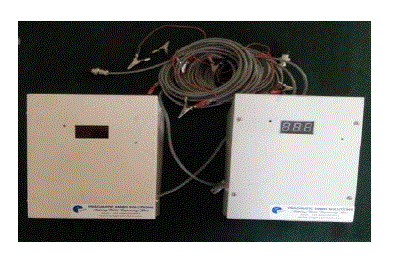 |
| An optical non-contact laser sensor, graphite rod and copper wire are used as two inputs to the velocity measuring device in figure 3.1. In the launcher facility, laser light at two points is interrupted by projectile inside the gun barrel also at two points closed circuit with graphite rod and copper wire. The circuit opens by hitting and breaking when the canister is launched. The distance in between these points would be 1m fixed before arrester. The time taken to travel these two points by the canister in the gun barrel is displayed in measuring device and the velocity could be evaluated. |
IV. METHODOLOGY |
| 4.1 Chapter Overview |
| This chapter presents the methodology involved in the design of High Velocity measuring device. |
| 4.2 Renesas RL78/R5F102AA Microcontroller |
| The centre part of the project is the microcontroller which is used to measure time and velocity of the canister. The microcontroller used in this project is a Renesas microcontroller which is a 30 pin microcontroller. It has the following features. |
| ROM: 16 KB, RAM: 2 KB, data flash memory: 2 KB |
| High speed on-chip oscillator : 24/16/12/8/4/1 MHz can be selected |
| On-chip single-power-supply flash memory (with prohibition of block erase/writing function) |
| Self-programming |
| On-chip debug function |
| On-chip power-on-reset (POR) circuit and voltage detector (LVD) |
| UART: 3 channel |
| I2C Protocol |
| 16-bit timer: 8 channels |
| Different potential interface: Can connect to a 1.8/2.5/3 V device |
| 8/10-bit resolution A/D converter: 8/11 channels |
| Standby function: HALT, STOP, SNOOZE mode |
| Power supply voltage: VDD = 1.8 to 5.5 V |
| Operating ambient temperature: TA = −40 to +85°C |
| The microcontroller is used as the monitor unit to process the input pulses and calculate the speed. The programmable counter measures the duration between two pulses. Counter is operated at the clock frequency of 24MHz. The simulation of hardware and software is done by using emulator E1 or E20 and CubeSute+ software. |
| Emulator |
| The emulator shown in figure 4.1 is a device to support the development of systems that uses the Renesas microcomputers. It provides support for system development in both software and hardware. The emulator is not guaranteed for use in the production line. The emulator is correctly used according to said purpose of use. |
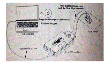 |
| This tool provides powerful support for the development of embedded applications for Renesas microcomputers. It has an emulator debugger function allowing the emulator to be controlled from the host machine via an interface. Furthermore, it permits a range of operations from editing a project to building and debugging it to be performed within the same application. In addition, it supports version management. |
| The count value is read by micro-controller, which calculates the speed using the formula, |
| S= D/ (C *T) |
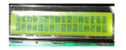
| Where S = Speed, D = Distance between two optical screens, C = No. of counts, and T = Counter clock period. The calculated speed is then displayed on the LCD screen as shown in figure 4.2. |
 |
| A liquid crystal display is a thin, flat electronic visual display that uses the light modulating properties of liquid crystals (LCs). LCs does not emit light directly. It consists of an array of tiny segments (called pixels) and to present the information that can be manipulated. |
| 4.3 Procedure for Conducting the Test |
| An acrylic fixture will fabricate to the pipe with dia of 18mm. |
| Then for each input required two acrylic fixture which is temporarily fixed by nut and bolt. |
| Then the transmitter and receiver are installed to the hole of the pipe. |
| A hole in which the laser beam will passed through the both hole. |
| Then connect to the electric supply to the register and the micro controller. |
| Cleaned the specimen is inspected ensure any contaminates adhered to surface. |
| Track the development in the testing of specimen and record the information for maintaining accuracy of the experiment and test. |
| The pipe in which the laser sensor is installed, the canister ice pellet will fire from the high pressure air tank will disturb the laser beam. |
| Microcontroller interfacing the sensor and the timers actuates the timer to arrest at the instant when the sensors sends and stop the signal. |
| When the laser beam is disturbed by the canister ice pellet, note down the time from the device. |
| The time freeze down in the timer and recorded in the memory location from where it send to the users. |
V. RESULTS AND DISCUSSION |
| Velocity is the rate of change of the position of an object, equivalent to a specification of its speed and direction of motion. Speed describes only how fast an object is moving, whereas velocity gives both how fast and in what direction the object moving. |
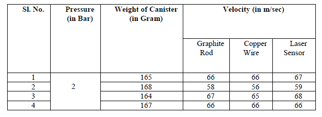
| The velocity of the canister ice pellet which is launched through the gun barrel is obtained from the velocity measuring devices. In this facility, the laser beams at two points is interrupted by the projectile inside the gun barrel, also two points closed circuit with graphite rods or copper wires, these circuit open by hitting and breaking when the canister launched. The distance between these two points would be 1m fixed. Thus the time taken to travel these two points by the canister could be evaluated and noted down which is tested at different pressure and different weight of the canisters are tabulated as given below: |
 |
 |
 |
 |
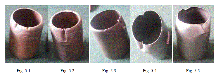
| Above Fig. 5.1 shows that collapsibility characteristic of canister at 2 bar pressure. Fig. 5.2 shows collapsibility characteristic of canister at 3 bar pressure, as weight of the canister varies collapsibility of front portion also varies and collapsibility seems more than the 2 bar. Fig. 5.3 shows collapsibility characteristic of canister at 4 bar pressure, as weight of the canister varies more collapsibility of front portion occur. Fig. 5.4 shows collapsibility characteristic of canister at 5 bar pressure, as weight of the canister varies collapsibility of front portion also varies at 5 bar buckling and overlapping of front portion can be observed due to the material flow. Fig. 5.5 shows collapsibility characteristic of canister at 6 bar pressure, as weight of the canister varies collapsibility of front portion also varies as pressure increased to 6 bar buckling and cracking of front portion the canister can be observed due to the material flow. |
| The canister fired from the ice pellet launcher impacts the arrester and get collapse at high pressure and the velocity of the canister is measured by high velocity measuring devices and it is tabulated above. |
VI. CONCLUSION AND SCOPE OF FUTURE WORK |
| Conclusion |
| The velocity measuring device is fabricated as per the requirement for the project. |
| The transmitters and receivers are installed at the launcher pipe at 1m of distance in the hole of the pipe from the end position. |
| The laser receiver receives the signal from transmitter and sends the information to the microcontroller to the data unit where the data stored and sends to the display unit where it shows the result. |
| The graphite rod or copper wire is also used as the signal transmitting media to the device as an input which gives the measured velocity of the canister ice pellet in the gun barrel |
| The high velocity released from the ice pellet canister launcher setup, the ice/bird impacts the target plate and this device shows the velocity of the ice pellet. |
| The pressure is varied to get the desired velocity and experiments were repeated. |
| The velocity is not increasing linearly as the pressure increased |
| The graphite rods input based device giving more accurate value compare to copper wires based device due to elongation. |
| We have tested the canister at different velocities to observe the collapsibility and characteristics of canister wall. |
| The high velocity measurement is accurate with help of the microcontroller; we got these values with slight difference from all devices. |
| Scope of future work |
| The velocity measuring device can use to test the velocity of many solid particles as the velocity calculated from the ice pellet canister launcher. |
| The development in the weapon to calculate the velocity and range of the weapon |
| The device can use to calculate the velocity of the solid particle through the pipe.In velocity measuring device circuit, different type of sensor can be used as input signals. |
| The device with sensor input can use to calculate the velocity of trains, buses and different types of locomotive running in the tunnel |
| The tests can be carried out by changing the length of the gun barrel, which can affect the velocity of the canister. |
| The impact load on the canister arrester by the canister moving with high velocity can be measure by adopting strain gauges mounting on the canister arrester bolt and that value can be achieved by strain gauge indicator device. |
| At different velocities we can observe the collapsibility and characteristics of canister on different geometry of canister and canister arrester. |
VII. ACKNOWLEDGEMENT |
| I would like to express my sincere gratitude to my Parents, Young and dynamic Principal, Beloved Head of the Department and my young and energetic Guide, without their support it would not have been possible to complete this project, also I would like to express my thanks to teaching and non teaching staff of our college. Last but not the least; I would like to extend my thanks to my friends who provided me valuable suggestion to improve my project. |
References |
|