Additive Manufacturing (AM) refers to a process by which components are built in layers by depositing material from 3D CAD data. CAD along with medical images and AM technologies has the capacity to create anatomical models that have diagnostic, therapeutic and rehabilitative applications. Disabled people require assistance for moving their lower limbs to enable them in the walking process. Exoskeleton is an assistive electromechanical device that are worn by a human operator and designed to increase the physical performance of the wearer. With the advent of new medical and manufacturing technologies, three-dimensional (3D) CAD model reconstruction from Computerized Tomography (CT) image has recently become a promising choice for exoskeleton design. The integration of CAD and medical technology is referred to as Bio-CAD modeling. The aim of the paper is to design a lightweight structure with a portable energy supply, without undermining the autonomy of the device. Initially the design is focused in designing an exoskeleton model to assist the knee joint and its associated structures to aid in walking. CT image of the lower limb is obtained from the patient in Digital Imaging and Communications in Medicine (DICOM) format.The CAD model of the stacked CT image is developed using Bio CAD modelling (MIMICS + 3-MATIC) software to obtain the final geometry of the Exoskeleton. The exoskeleton model may be fabricated in AM system with Acrylonitrile Butadiene Styrene (ABS) material, and tested for its compatibility in real time. The combination of AM and Bio CAD modelling gives a high level of accuracy in terms of shape, size and position of the Exoskeleton and significantly shorter lead time when compared to the conventional (manual) technique. It also provides more comfort to the patients while walking, standing and sitting conditions.
Keywords |
| Additive Manufacturing, Bio CAD Modeling,
Lower limb Exoskeleton, Rehabilitation, Customization. |
INTRODUCTION |
| The realization of wearable robots for rehabilitation of
neuromuscular patients has seen in 21st century. Because
a neuromuscular disease leads, the patients in pathetic
condition due to the causes of mobility impairments and
depending on the affection level, gait may be affected
drastically making it even impossible. In 1960s, the first
robot introduction in the industrial workplace [1], that
have developed at an incredible rate and now encompass
almost every aspect of modern society. Wearable robots
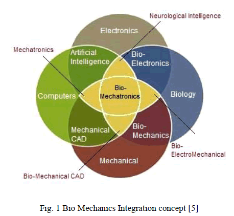
are defined as “a mechatronic system that is designed
around the shape and function of the human body, with
segments and joints corresponding to those of the person
it is externally coupled with” [2].The exoskeleton was
implemented for rehabilitation, while individual who
have lost their motor functions in their lower limbs. |
 |
| The main concept of using an exoskeleton for
enhancement or protection has been around for hundreds
of years. However, it was the powered exoskeleton makes
reality.”HARDIMAN” is one of the first powered
exoskeleton; it gives contribution for early development.
In 1960s, General Electric Co. had designed a full body
exoskeleton, comprising an inner and outer exoskeleton
which operated on a master control scheme [3]. The major
developments in exoskeleton systems has been achieved
at last five years [2].System such as the Berkley’s
BLEEX, display cutting edge modern technology and
Hybrid Assistive Limb (HAL), which is now in the fifth
generation. The researchers at the University of Tsukuba,
Japan has been designed a HAL- 5 system and aimed at
meeting both rehabilitation requirement and strength
augmentation. |
| Two control schemes namely “Cybernetic robot
control” and “Bio- cybernetic control” which is used to
control a full body exoskeleton of HAL -5 [4]. Bio –
cybernetic control utilizes the Electromyography signal
for augmenting operation. Cybernetic robot control is
used for repetitive activities. There is no viable EMG
signal used in this controlling scheme. The University of
California, Berkley researchers developed a BLEEX
lower limb exoskeleton. The operator movement is
predicted by sensors, placed on the exoskeleton. The main
aim is to improve the operator load bearing capability at
the same time Interaction force between the operator and
exoskeleton is not measured through any sensors [6].
Motor disorder patients are effectively rehabilitated by
exoskeleton robotics, which is derived from mechanical
and biomedical technology. Much research has been done
for improving the strength beyond the limits of human
being, but this information has been looked at for
augmenting exoskeleton for military purpose. Interaction
between the exoskeleton and user has been done by
wearable pieces of robotic exoskeletal structures. |
| Incorporating the use of exoskeletal robotics in treating
myopathy patients who possess motor function disorders
is pertinent in making successful in the medical field and
whose motor functionality has been compromised by
recovery process. Neurological injuries or disorder cannot
be fully recovered by physical therapists. The important
aspect of future technology will be a continual
development of combination of biomedical and
mechanical technology [7].Sarah Webster et al [8]
designed and fabricated an Assistive Device for Emma
Lavelle. She was diagnosed with arthrogryposis multiplex
congenita (AMC), a non-progressive condition that causes
stiff joints and very underdeveloped muscles. Emma was
born with her legs folded up by her ears and her shoulders
turned in. Emma was introduced to the Wilmington
Robotic Exoskeleton (WREX), Wilmington Robotic
Exoskeleton (WREX), an assistive device made of hinged
metal bars and resistance bands. |
| They are preferred an Additive process to fabricate a
WREX device, because easy to build complex human shapes with particular finishes. The aluminum and steel
device was a lifesaver for Emma, which helped her to
pick up objects and lift her arms toward her mouth for the
first time. But the supporting structures were heavy for
little Emma, so as an alternative, printed structure with
light weight ABS material was designed. |
| Surachai Panich et al [9] designed and fabricated a
lower limb exoskeleton for rehabilitation. The typical
habilitation for lower limb is separated in three types,
which are active, passive and active –assistive mode.
Active mode is one important aspect of rehabilitation for
increasing or maintaining joint function providing
appropriate resistance to the muscles to increase
endurance and strength. The relative positions of each
joint are determined by Denavit- Hartenberg method. |
| A semi-automated methodology consists of Computer-
Aided Design (CAD) and Additive Manufacturing (AM)
technologies was developed for Exoskeleton
development, and demonstrated in a real-life case. The
correct geometry of Lower limb is ensured by stacking
the Computed Tomography images of patient in reverse
order and joining them using a medical modelling
software program. The CAD model of the stacked CT
image is developed by using 3-MATIC software, to
obtain the final geometry of the Exoskeleton. The CAD
model is incorporated with the actual model, the
simulation is done to find the user comfort and also the
required muscle force for the various actions that
includes walking, running, climbing, and etc., Final
Exoskeleton models will be fabricated in AM systems,
and its used for fitting it in patient’s lower limb. The
quality of life for the people has been improved due to
the impact of advancing modern medical technology. |
TECHNICAL D EVELOPMENT |
| The exoskeleton has been categorised in to two
different lines based on the technical development; the
mechanical development including actuator selection and
the electronic systems development including controls
system, sensors, and Data acquisition system [10] |
| The bio mechanical analysis of the human morphology
and the human gait is used for mechanical development.
Based on the analysis result we have to select a suitable
drives for muscles actuation, because the exoskeleton
must be able to support patients during gait and make
more comfort to the patients in an ergonomic way. This
concept includes both drives design and mechanical
structural design. In this direction, experimental analysis
has been performed for the preliminary exoskeleton; a
complete knee model from the entire lowerlimb has been
designed. |
| The control system of the exoskeleton includes the
method to identify the user intention and decision is made
to support patient in an adequate way during gait with the
required torque in each joint. From these data, torque of
the knee joint has been considered to select a proper
control system. In the modular development, the control
system makes to achieve robust system [11] [12]. Initially knee joint prototype has been produced in order to test and
validate the control systems of knee exoskeleton. The
control system of full lower limb exoskeleton has been
launched based on results of knee joint prototype. |
MECHANICAL ST RUCTURAL DESIGN |
| The structural design and drive designs are considered
as the mechanical development of exoskeleton. Actually,
selection of proper drives and adequate mechanical
structure is a challenging task because during gait, the
human joints require high torques but at the same time, the
structure must be compact and adopt with low weight
drives to overcome the aesthetic issues [10] |
| A. Design of Drives |
| In these knee exoskeleton, to determine which degree
of freedom have to be actuated and analysed the most
common daily live activities: gait cycle, going upstairs,
going down stairs, standing up and sitting down. The three
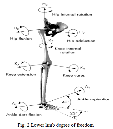
primary joints comprises from the lowerlimb of the human
skeleton, namely hip, knee and ankle. In fig 2 the Degree
of freedom of each joint conditions are illustrated [4]. In
this work mainly focused on the motion of the system and
initially neglected the stability of lowerlimb. Since main
aim is to rehabilitate the motion of a patient knee joint. In
the walking cycle, internal rotation, hip abduction and hip
adduction do not play a significant role [13], and were
eliminated from the design. The ranges of motion for the
joints are constrained such that hyper‐extension and
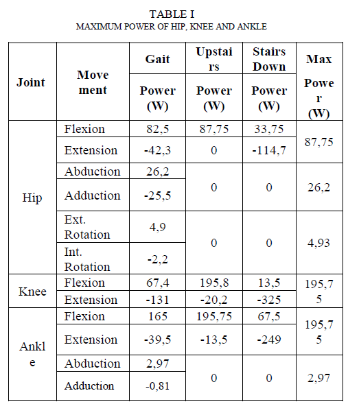
hyper‐flexion do not occur. Table 1 shows these ranges of
motion [14]. |
| The knee DOF was actuated, while the hip and ankle
joint was designed to be passive. The joint torques for the
actuated DOF has been determined by the evaluated data
from clinical gait analysis [15].The torque required for
knee extension during stair climbing was 140 Nm and 50
Nm during walking. Actuators were selected such that the
maximum torque was met, which allows for the operator
to be raised or lowered from a seated position. When
compared to direct mounted rotational actuators, the linear
actuators offered a high speed/load capabilities and less
bulky design. |
 |
| In the lowerlimb joints forces, power and angle pattern
data in the sagittal plane have been largely studied [16],
[17] Different gait experiments have been conducted to
arrive a data of gait cycle for the exoskeleton drive
calculation [17]. This experiments are developed in
normal conditions by regular size users and at normalized
speed. For the biomechanical consideration this data
gives an enough precise base, even though this data
depends on user involved in experiments. If the patient
has balance through well controlled external balance aid
system, the lack of force in the sagittal plane will impede
to perform the most of the daily live movements.
Therefore three degree of freedom are mechanically
actuated like, hip flexion – extension, the knee flexion –
extension and ankle dorsal – plantar flexion. In this work
consideration hip and ankle degree of freedom are not
considered. |
 |
| In this first mechanical prototype the knee flexion –
extension are driven by pneumatic muscles actuators. The
most appropriate drives for the exoskeleton has been
determined by based on the specifications of each
actuated degree of freedom table I [18].In this drive
selection the volume, the weight and the aesthetic also
have to be considered. |
| Three different actuators are considered for
exoskeleton actuation like, hydraulic cylinders, electrical
motors and pneumatic muscle actuators. |
 |
| In knee joint hydraulic cylinders are situated
transversally for actuation of joints. The pneumatic
cylinders have angle restriction during gait condition and
the patient will have more difficulties to sit down.
Minimum 20 kg total weight of hydraulic system has been
estimated excluding batteries, electronic and control while
all system has been determined. As a result, hydraulic
system has been ruled out and shifted to another
alternative way, to actuate the exoskeleton. |
| The second choice is the electrical motors. This choice
would simplify the design and the aesthetic effect is
considerably lower than with the other options. Finally
these devices are not preferred for the actuation of joints;
it’s usually heavy and bulky, affecting their practicality in
the daily motion assistance. |
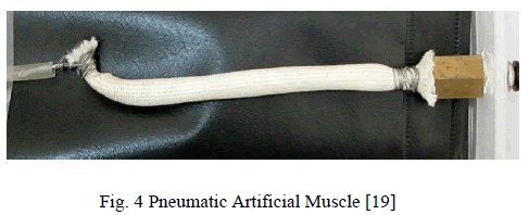 |
| The third option is Pneumatic Artificial Muscles
(PAM) use as actuators, due to their lightness, flexibility
and their capacity to produce a high amount of force. To
reach the specifications needed in each actuated knee joint
the muscles would have a diameter greater than 20 mm
and a weight is less than 800g. Moreover as they are
simple effect actuators, two muscles are necessary to
actuate each dof that means 1600g considering only the
PAMs without any other additional system. In this kind of
actuation, the high torque requirement of the joint is a
problem that needs to be solved. |
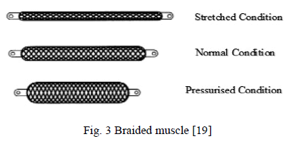
| The artificial muscles developed in the Bioengineering
Laboratory [20], [21] consist of an internal latex bladder
surrounded by a braided nylon shell that is attached at
either end of the fittings. When the internal bladder is
pressurized, the high pressure air or gas pushes against its
inner surface and against the external shell, and tends to
increase its volume. Due to the braided nylon shell
properties, the muscle shortens according to its volume
increase and, if it is coupled to a mechanical load,
produces tension. |
| Finally the designed drive shown in Fig.4 has a
dimensions of 30mm Diameter and 202.35 mm length. |
| B. Structural Characteristics of exoskeleton |
| The main aim is to design a suitable exoskeleton for
most muscular disorder peoples. The changes in
anthropometric measurements depending on weight,
height, sex. Some important factors are considered during
the exoskeleton design to cover different physiognomies
of people in a height range from 1550mm to 1850 mm:
the thigh is adjustable from 380 to 470mm and the calf
from 360 to 450 mm [22]. One more important aspect to be considered is the easiness of the exoskeleton’s
regulation. Quick adjustment method with simple
butterfly screws and belt arrangement has been included. |
| The range of motion of each joint is considered as
important one while designing the mechanical structure
of the exoskeleton. The exoskeleton can’t move farther
than beyond the minimum range of movement of patient
in each joint in order to avoid any damage but at the same
time it must allow free movements to wearer with in the
ranges of motion required during gait or sitting down.
Regarding this range of motion in each joint are a bit
smaller than values allowed by the biomechanical joints
to avoid any kind of injuries. The patient comfort is one
of the important consideration in structural design
process of exoskeleton and also consult with orthopedics
specialist for getting assurance to using materials and
shapes,because the structural elements are in contact with
the user and it assures the patient comfort but rigid
enough to guarantee the transmission of the movement to
the patient. |
| IV.CUSTOMIZED EXOSKELETON STRUCTURAL DESIGN |
| The design of exoskeleton suit are carried out by using
Bio CAD modeling software ( Mimics & 3 Matic
software)(Figure 5).Reverse engineering techniques used
for developing a structure of exoskeleton. Because
anotomy of Human lower limb is very complicated shape.
So the dimensions of the structures are obtained from the
patients CT scan in DICOM format.Advanced 320 slices
CT scanner is used for taking the image. Slice thickness is
1mm. Minimum slice thickness can lead to higher
accuracy of solid model and avoid reconstructing a
slices.After that slices of the DICOM data are imported to
MIMICS software.All the slices are stacked together and
converted in to solid model by using 2D segmentation and
3D region growing techniques.Initialy creating a mask for
Thresholding operation,it has been used to increase a
density of soft tissue (muscles) and Hard tissue (Bone). |
| Select a particular region (knee) of lowerlimb based on
the requirement (in no of slices) of corresponding
dimensions. Edit a mask whether draw it or erase the
slices. |
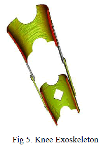 |
| Then generate a solid model for the corresponding
mask.Measurements are taken using scaling options. After
the solid model conversion, 3Matic modeling software
used to modeling a structure of exoskeleton with supporting arrangements.Setting a scale factor 1:1 uniform
thickness level. By using Boolean operation to form a top and bottom brace structure. Then smoothening
operation is performed on the edges and surface of the
braces for removing a sharp corner. Select a fit plane and
create a suitable location for actuators and sensors
placement. In both sides, supporting arrangement also
created using CAD tool at corresponding plane. Figure 5
shows the design model of knee exoskeleton. This model
will be fabricated by AM techniques. |
CONC LUSION |
| In this work, customized exoskeleton is targeting a
specific pathology, it will benefit to the patients with
muscular disorders. Regarding the patients, a
biomechanical analysis has been made in order to
determine the common characteristicsthat the patients
will be benefitted from the exoskeleton (weakness,
balance control, Lowerlimb mobility control). It’s
providing better conditions to develop a standard gait next
to the physiological one. One of the important aspect of
patient comfort has been achieved by using reliable
technique of Bio CAD modeling with additive
manufacturing for the purpose of customization.
Advances in actuation technologies of Pneumatic muscle
actuator gives benefit to the user during sitting and gait
condition, and also it provides more strength. |
ACKNOW LEDGMENT |
| The authors would like to thank DST-NHHID for
MIMICS, 3-MATIC softwares. |
References |
- J. J. Craig, Introduction to Robotics -Mechanics and Control 3rded., Upper Saddle River: Pearson Prentice Hall, 2005.
- S. Mohammed, and Y. Amirat, "Towards intelligent lower limbwearable robots: Challenges and perspectives - State of the art, "IEEE International Conference on Robotics and Biomimetics,2008, pp.312-317.
- J. L. Pons, Wearable Robots: Biomechatronic Exoskeletons,Chichester, West Sussex: John Wiley & Sons Ltd, 2008.
- Y. Sankai, "Leading Edge of Cybernics: Robot Suit HAL, "SICE-ICASE, International Joint Conference, pp. 1-2, October2006.
- D. Naidu, R. Stopforth, S. Davrajh, and G. Bright, âÃâ¬ÃÅA PortablePassive Physiotherapeutic Exoskeleton,âÃâ¬Ã International Journal ofAdvanced Robotic Systems, InTech, Vol 9, August 2012.
- H. Kazerooni, J. L. Racine, H. Lihua, and R. Steger, âÃâ¬ÃÅOn theControl of the Berkeley Lower Extremity Exoskeleton(BLEEX),âÃâ¬Ã IEEE International Conference of Robotics andAutomation, pp. 4353-4360, 2005.
- J. L. Pons, âÃâ¬ÃÅRehabilitation Exoskeletal Robotics,âÃâ¬Ã Engineering inMedicine and Biology Magazine. IEEE, vol.29, no.3, pp.57-63,May-June 2010.
- Sarah, and Webster, âÃâ¬ÃÅA custom 3D printed version of theWilmington Robotic Exoskeleton (WREX) empowers littleEmma to use her arms despite arthrogryposis,âÃâ¬Ã AdditiveManufacturing: A custom solution for the medical industry, April2013
- P. Surachai, âÃâ¬ÃÅDesign and Simulation of leg Exoskeleton suit forrehabilitationâÃâ¬Ã Global Journal of Medical research Volume 12,Issue 3 Version 1.0, pp. 2249-4618.
- H. Zabaletal, M. Bureau1, G. Eizmendi1, E. Olaiz, J. Medina, andM. Perez, âÃâ¬ÃÅExoskeleton design for functional rehabilitation inpatients with neurological disorders and stroke,âÃâ¬Ã GuttmannUniversitary Institute for Neurorehabilitation-UAB, Badalona.
- L. David, and Parnas, "On the Criteria to Be Used inDecomposing Systems into Modules," Tech. report, ComputerScience Department, Carnegie-Mellon University, August 1971.
- D. J. Mayhew, âÃâ¬ÃÅPrinciples and Guidelines in Software UserInterface Design,âÃâ¬Ã Prentice Hall PTR; 2006.
- K. Hian Kai, M. Missel, T. Craig, J. E. Pratt, and P. D. Neuhaus,"Development of the IHMC Mobility Assist Exoskeleton,âÃâ¬Ã IEEEInternational Conference in Robotics and Automation, pp.2556-2562, 2009.
- D. Naidu, C. Cunniffe, R. Stopforth, G. Bright, and S. Davrajh,âÃâ¬ÃÅUpper and Lower exoskeleton limbs for Assistive andRehabilitative Applications,âÃâ¬Ã 4th Conference of Robotics andMechatronics, Pretoria, South Africa, November 2011.
- R. Riener, M. Rabuffetti, and C. Frigo, âÃâ¬ÃÅStair ascent and descentat different inclinations,âÃâ¬Ã Gait & Posture, vol. 15, pp. 32-44.
- B. Dejan, T. Popovic, and SinkjÃÆær, âÃâ¬ÃÅControl of Movement forthe physically disabled,âÃâ¬Ã Center for Sensory-Motor Interaction,Aalborg University, 2003.
- J. Linskell, CGA Normative Gait Database, Limb Fitting Centre,Dundee, Scotland, Young Adult. Available:http://guardian.curtin.edu.au/cga.data/
- D. A. Winter, The Biomechanics and Motor Control of HumanGait: Normal, Elderly and Pathological. Second. Edition.Waterloo: University of Waterloo Press, 1991
- RanjeetRajan, P. K. Upadhyay, Arbind Kumar, and PraveenDhyani, âÃâ¬ÃÅTheoretical and Experimental Modeling of AirMuscle,âÃâ¬Ã International Journal of Emerging Technology andAdvanced Engineering, ISSN 2250 âÃâ¬Ãâ 2459, Volume 2, Issue 4,April 2012.
- D. A. P. NAGEM, Development and performance test of theMckibben artificial muscle, Graduation Work, MechanicsEngineering Department âÃâ¬Ãâ UFMG, 66p, 2002.
- UFMG. Marcos Pinotti, DaniloNagem. AtuadorfluidomecÃÆânicode fÃÆácilmontagemconstituÃÆÃÂdo de doistubosmaleÃÆáveis e sistemade fixaÃÆçÃÆão de anilhas. BR. n. MU8203338-2., 27 dez. 2002, 09set. 2003.
- D. B. Chaffin, and G. B. J. Anderson, âÃâ¬ÃÅOccupationalbiomechanicsâÃâ¬ÃÂ, John Wiley & Sons, 1991, pp. 80.
|