ISSN ONLINE(2319-8753)PRINT(2347-6710)
ISSN ONLINE(2319-8753)PRINT(2347-6710)
Parag Wanjari 1, K.M.Narkar 2
|
| Related article at Pubmed, Scholar Google |
Visit for more related articles at International Journal of Innovative Research in Science, Engineering and Technology
Electrostatic Precipitator is the device used for controlling air pollution. This is used for cleaning of boiler process gases. Process gases contain suspended dust particles. These dust particles are collected on collecting electrodes. The effectiveness of Electrostatic Precipitators is affected by various factors. Periodic cleaning of collecting system plays a major role. Dust gets deposited on collecting electrodes and dislodged by means of vibrations of collecting electrodes. For huge volume of process gas the size of Electrostatic Precipitator will also be large. Since space is major constraints the ultimate solution will to go vertically i.e. increase the height and accordingly the collection area. Since the height is increased old methods of rapping will be ineffective and hence the new methods introduced to increase the vibration. Time is another major constraint for checking of such continuous improvements. So simulation and further physical measurement is more practical method. This paper presents FEA concept of modelling and analysis of collecting electrodes of an Electrostatic Precipitator by Implicit Transient Dynamic Analysis. Experimental testing is done for validation. The results of FEA concept and physical measurements are discussed.
Keywords |
| Collecting Electrodes, Rapper, Anvil, Electrostatic Precipitator (ESP), Vibration analysis, FEA. |
I. INTRODUCTION |
| Industrial process gases contain dust particles. This is a big problem of industrial air pollution and has to be controlled. There are various air pollution controlling equipments available in the market like Electrostatic Precipitator (ESP), Bag filters, Cyclones, Mechanical dust collector etc. Apart from this Electrostatic Precipitator is one of the most popular and often used device to remove the dust from process gases. The effectiveness of Electrostatic Precipitator depends on parameters like gas flow condition, electric field generation and geometric parameters. |
| The time to time cleaning is a major activity which is rather the cause of dust collection. The collecting electrodes are cleaned periodically on which dust is collected. Efficiency of ESP depends on the periodic cleaning of collecting electrodes [1]. The dust is removed by introducing the vibrations of collecting plates by means of rapping [2]. The rapping system generates the vibration of collecting plates and due to vibrations the dust layer available on collecting electrodes will get detached and further collected in dust hoppers. |
| The vibrations of collecting electrodes plays major role and improves the ESP effectiveness and performance. The vibrations created by means of gravity & electrically operated rapping system. The rapping system includes the rotating hammer mounted on the common shaft and arranged in such a way that the cleaning will be periodic.Thus effective working of rapping system plays important role in dust removal process. Different accelerations are developed at different locations of the system. Accelerations are mainly depends on both energy of the hammer at the moment of impact and the way in which the force is transferred to the collecting electrodes and also Geometrical features of the electrodes (shape, length, thickness). Impact force generated by the hammer have an essential influence on tangent and normal accelerations at different points of the plates, and thus on the effectiveness of the dust removal process [3]. |
| Researchers have done various experimental studies to ensure effective removal of dust from collecting electrodes of ESP, from that they derived various useful conclusions for further study and work. However this experimental approach has major drawbacks of higher time lines and cost involved in physical testing. To overcome this drawback there is need to develop a quick and reliable process to evaluate the vibration performance of Electrostatic precipitator. |
II. LITERATURE SURVEY |
| The paper reviewed are referred and used directly or indirectly for completing this work. The present project work is based on the studies carried out by various researchers on ESP and vibration performance evaluation of collecting electrode. These papers are. |
| Andrzej N.[1] The paper presents a numerical model for simulating the vibration of collecting electrodes in an electrostatic precipitator. The finite elements (FEM) method was used to describe the shell elements of the collecting electrodes. The remaining elements of the system were modelled with the application of the rigid finite elements method (RFEM). Measuring validation and testing calculations results are presented. The Vibro ESp calculation software is used. The presented FEM model was extended by introducing RFEM models of suspension and anvil beams, and implemented into VibroESP calculation software. The results are Validated by comparing the results of numerical simulations with measurements performed on a test stand built by a producer of electrostatic precipitators. |
| Andrzej N. and Wojciech S.[2] presents the results of research into changes in vibrations of collecting electrodes are presented in the paper. The changes come from the optimisation of geometric and dynamic parameters of the shaking down system in electrostatic precipitators (ESP). The computational verification was carried out using the finite element method on the MSC NASTRAN package. Vibrations and accelerations of the collecting electrodes were measured. The results were used in the comparative analysis and the analysis of spectral density of acceleration power. |
| Iwona A., et al.[3] presented two new methods in modelling the collecting electrodes which enable us to analyse vibrations of the ESP system. The first method called a hybrid finite element method which combines the rigid finite element method and the finite element method. The model involves a large number of degrees of freedom which affects the required calculation time. Since geometrical properties do not vary along the length of the collecting electrode, the second model is formulated using a semi-analytical process the finite strip method. |
| Neundorfer M., [4] presented methods for improving electrostatic precipitator performance by increasing electrode excitation level during rapping and by optimizing rapping control. Design modification can reduce mechanical impedance to vibration transmission during rapping. These same modifications can eliminate areas of high stress concentration where fatigue failure often occurs. Rapping system control parameters are presented as they relate to variations in field collection and shedding rates. Methods for optimizing field rapping repeat rates using available opacity, ash pull, and precipitator power information are discussed. |
| Manyin H. et al. [5] presented that the normal operation of the vibration equipment and the dust removing equipment of ESP is an important factor to ensure ESP in a safe, stable and efficient running and has a direct influence on the efficiency of ESP and the working life of the related equipments. |
| Kim S. and Lee K. [6] have done experimental study of electrostatic precipitator performance. They have designed, built and operated a laboratory-scale single-stage electrostatic precipitator (ESP) in a wind tunnel. As a first step, a series of experiments were conducted to seek the operating conditions for increasing the particle collection efficiency by varying basic operating parameters including the wire-to-plate spacing, the wire radius, the air velocity, the turbulence intensity and the applied voltage. As the diameter of the discharging wires and the wire-to plate spacing are set smaller, the higher collection efficiency has been obtained. |
III. DETAILS OF ESP RAPPING SYSTEM |
| The ESP is so arranged that the collecting plates are kept parallel. The collecting plates are kept in hanging condition. The top side is connected with Top Hangers and bottom is with Bottom Hanger. Dusty gas is allowed to pass through this passage of collecting plates. The anvil is assembled at one side at bottom and middle of collecting plates. Rotting hammer is so arranged that the rapping should be regular, alternate and periodic. |
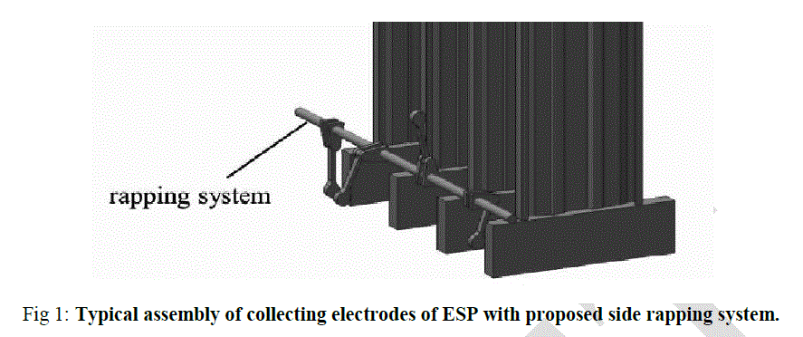 |
| Fig 1 shows the typical arrangement of the collecting plates and rotting hammer. The hammers are mounted on rotating shaft which is connected to electric geared motor. The vertical panels are collecting plates with anvil at bottom. Hammers are so assembled that rapping will be continuous but at alternative collecting plates. |
IV. FEA MODELS AND ITS DETAILS |
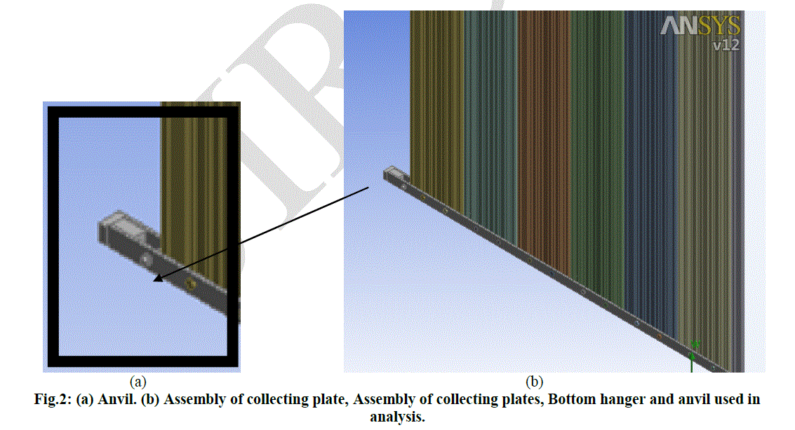
| Looking at complicated geometry and huge size, FEA is best approach for analysis. Analysis is done by using commercial software. The collecting plates are made up of shell 63. Support Girder, Anvil, bolt, top and bottom hanger are made up of solid45. Support girder, and the connection of top hanger are considered as fixed. The analysis is done by using Ansys software. |
 |
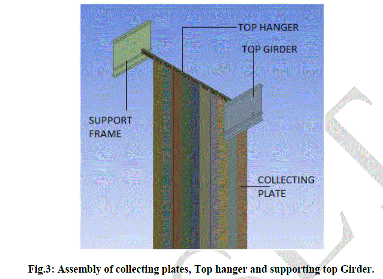 |
| Fig. 3 shows assembly of the model used for analysis. The top side of collecting panels includes top girders, top hangers, Support frame etc. The arrangement is clearly shows that how the collecting panels are kept in hanging condition. |
V. ANALYSIS METHOD |
| Following analysis is done for evaluation of collecting plate vibrations: |
Transient analysis: |
| Hammer hitting operation is transient event which depends on time taken for completing one hitting cycle. So the conventional static analysis is not suitable for such analysis. Implicit transient analysis is best solution for simulation of such events. |
| This approach is appropriate to study the system response. The response such as amplitude is precisely measured by this method. |
| In this procedure, the analysis is carried out to measure plate displacement when hammer hits the anvil. System response is measured for 3.5sec from the time of impact. The pulse width is required to be estimated to determine the impact force. Impact acceleration is calculated by means of rate of change of velocity during the pulse band width. Impact occurs when there is steel on steel impact. The peak value is calculated from following equation: |
 |
| The calculated impact force is applied on anvil. Transient analysis is carried out to find the magnitude of displacement at various points of collecting plate. Practically it is observed the dust is deposited at the middle and bottom side of collecting plates. As the dusty gas moves forward the dust will try to accumulate on middle and bottom side of collecting plate due to gravity. The traditional top rapping system will not be effective with increase in collecting plate height. So to improve this side rapping is introduced. To take the results, the readings are taken on collecting plate at top, at middle and at bottom portion of collecting plate. |
| The measurements are taken at region of 1m from top and bottom and middle part of the region. |
VI. EXPERIMENTAL RESULTS |
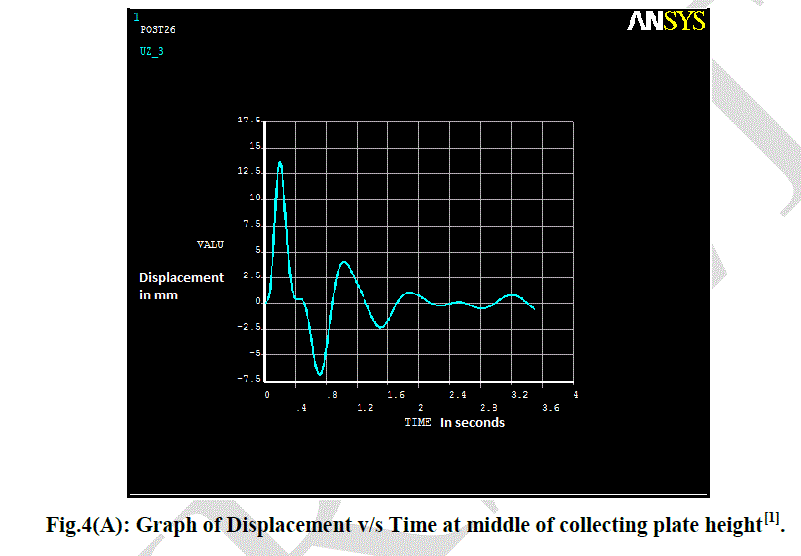
| The analysis is carried using Ansys Software. FEA results and onsite measurement is well within the limits and shown good agreement. It has been observed from the result that the response is higher for first 0.5 to 1sec. Further its getting damped. So the analysis is carried out for 3.5sec time span. |
 |
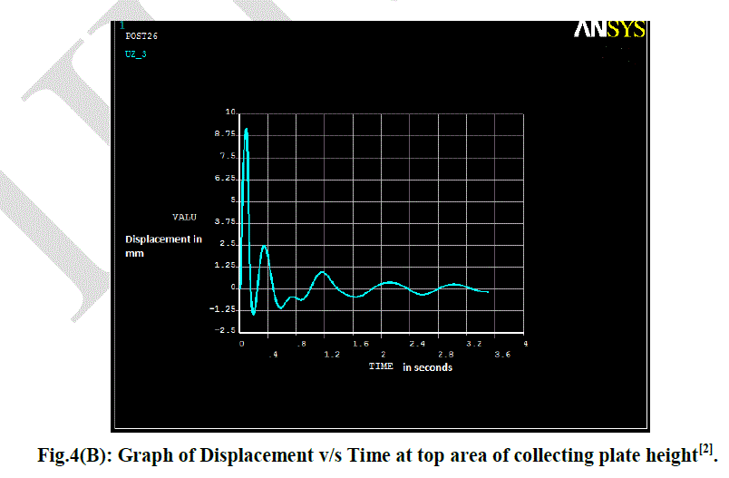 |
| Fig. 4 shows the displacement at different location of collecting plate. The commercial Ansys Software is used to analyse the model. The impact force is calculated and applied to anvil. Implicit transient analysis is carried out and final output are shown in the Fig.4 above. |
VII. VALIDATION OF RESULT |
| The analysis result is validated by comparing the results with actual onsite measurement. The onsite equipment is complicated. The measurement is done in various sets since there might be chances of human error considering the criticality of the component. The instrument Vibration analyser is used for measurement of vibrations. |
| Following are the final results of plate displacement comparison: |
 |
| Table 1 gives the results obtained from Ansys software and on site measurement. The measurements are carried out at three different regions of entire collecting plate height. |
VIII. CONCLUSION |
| Impact location of rapper plays important role in vibration level of collecting plate. There is good agreement between FE analysis and onsite testing. Side rapping system is more effective than top rapping for cleaning of collecting plates. Maximum displacement is occurring at middle of the plate and minimum at the bottom. |
References |
|