ISSN ONLINE(2278-8875) PRINT (2320-3765)
ISSN ONLINE(2278-8875) PRINT (2320-3765)
Prabhaker Singh1 and Mr. G. S. Tripathi2
|
| Related article at Pubmed, Scholar Google |
Visit for more related articles at International Journal of Advanced Research in Electrical, Electronics and Instrumentation Engineering
To have an efficient communication, an antenna plays a major role to transmit signal, keeping this in mind we have designed a low profile Microstrip antenna. In this paper we have designed a compact size polygon shaped patch Microstrip antenna and simulation has been done using IE3D simulator software version 15.2. The proposed antenna is excited through coaxial feed technique. The dimensions of antenna are 50mm×60mm (Ground plane), 40mm×40mm (patch), and substrate thickness of 1.6mm and FR4 material is used as dielectric having relative permittivity of 4.2 and loss tangent of 0.0013. Various parameters such as return loss, VSWR, bandwidth, gain, efficiency, etc. have been studied.
Keywords |
| Polygon patch, Microstrip antenna, IE3D, Coaxial feed. |
I. INTRODUCTION |
| Microstrip antenna (MSA) received considerable attention in early 1970âÃâ¬ÃŸs, although the first design and theoretical models were appeared in 1950âÃâ¬ÃŸs. In its most basic form Microstrip patch antenna consist of a radiating patch on one side of the dielectric substrate and ground plane on the other side. The patch is generally made of conducting material such as copper or gold and takes any possible shape. The radiating patch and feed line is usually photo etched on the dielectric substrate. MSA radiate primarily because of the fringing field between the patch and the ground plane. For good antenna performance, a thick dielectric substrate having low dielectric constant is desirable since this provide better efficiency, larger bandwidth and better radiation, such antenna configuration leads to large antenna size. In order to design a compact Microstrip patch antenna a large dielectric constant material is used. They are applicable for many applications: Mobile communication, Satellite communication, aircraft etc. MSAs are increasing in popularity for use in wireless application due to their low profile structure. Therefore they are extremely compatible to embedded antennas in handheld wireless devices such as cellular phones, pager, etc. MSA suffers from some disadvantages such as narrow bandwidth, low efficiency and low gain. MSA has a very high antenna quality factor (Q). Q represents the losses associated with the antenna. MSA can be excited by variety of methods which are classified in two categories, contact and non-contact. Contact feeding methods are coaxial probe feed and Microstrip line feed and non-contact feeding methods are proximity couple feed and aperture couple feed. |
II. ANTENNA DESIGN METHODOLOGY |
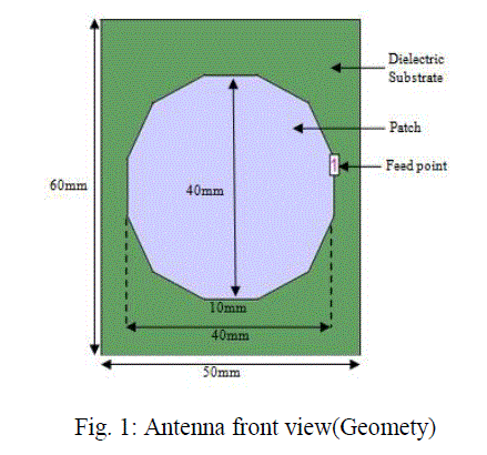
| The proposed antenna is designed on the simulator tool IE3D version 15.2. Dimensions of the proposed antenna are Ground plane (50×60) mm, patch size (40×40) mm, substrate thickness 1.6mm and FR4 (dielectric constant=4.2, loss tangent = 0.0013) is used as dielectric material. Coaxial probe feed technique is used for the excitation of antenna. Feed point to feed the proposed antenna is (45, 33.775, and 1.6). Coaxial connector is mounted at that point to connect with the transmission line. The geometry of the proposed antenna is shown in figure 1. |
 |
III. RESULTS AND DISCUSSION |
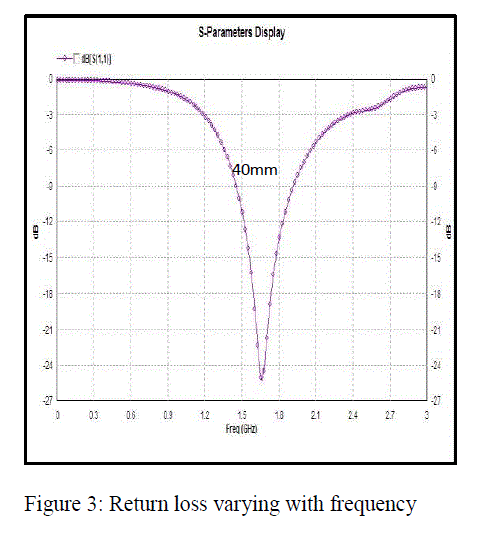
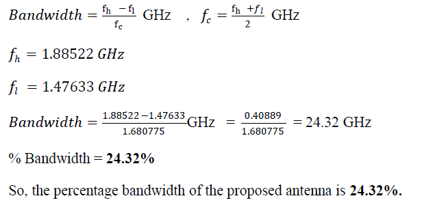
| Parameters such as return loss, bandwidth, VSWR, gain, antenna efficiency, radiation efficiency and axial ratio are being discussed for the proposed antenna. Bandwidth of an antenna is being calculated using a return loss curve or Sparameter display. Bandwidth is being calculated along -10 dB return loss curve and it is observed that the lower and higher frequencies are 1.47633 GHz and 1.8852GHz. The return loss of the proposed antenna is -25 dB at 1.65GHz center frequency. |
 |
 |
| Bandwidth of the proposed antenna is being calculated using formula given as: |
 |
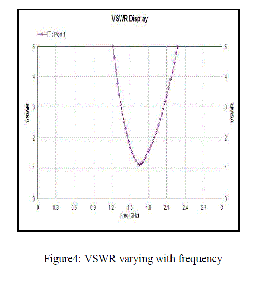
| Whether the Bandwidth of an antenna is useful or not is being justified by the VSWR curve i.e. both the frequencies must lie below 2 dB. It is shown in the above VSWR curve (Figure 2) that both the frequencies are below 2dB. |
| Total Field Gain of the proposed antenna is calculated using the curve between gain and frequency. The gain of the proposed antenna is 2.3786 dB at 1.8265 GHz as shown in figure 4. |
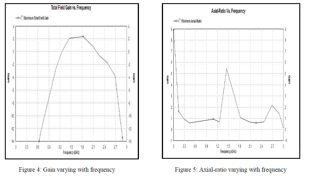 |
| Axial ratio of the proposed antenna is 0.205637 dB (minimum) at 2.99 GHz as shown in the figure 5. |
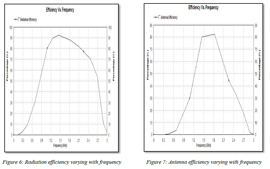
| Efficiency of an antenna is classified as radiation efficiency and antenna efficiency. The radiation efficiency of the proposed antenna is 92.3057% at 1.4479 GHz frequency and Antenna efficiency is 82.3729% at 1.8765GHz frequency. Figure 6 and 7 shows the graph of radiation efficiency and antenna efficiency varying with frequency. |
 |
IV. CONCLUSION |
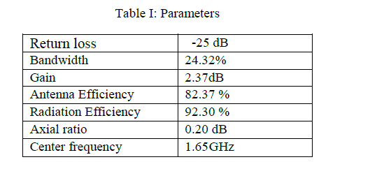
| In this paper, performance of 12 sided polygon shaped patch Microstrip antenna is being investigated using IE3D software, Design and simulation tool (version 15.2). Various parameter of the proposed antenna such as: return loss, VSWR, efficiency, gain and axial ratio are shown in the table 1. |
 |
V. ACKNOWLEDGEMENT |
| The Authors would like to thanks to the department of Electronics and Communication Engineering “Madan Mohan Malviya Engineering College” to support us in research work. |
References |
|