ISSN ONLINE(2278-8875) PRINT (2320-3765)
ISSN ONLINE(2278-8875) PRINT (2320-3765)
Chandan Kumar Jha1, Mahendra Singh Bhadoria1 , Avnish Sharma1, Sushant Jain1
|
| Related article at Pubmed, Scholar Google |
Visit for more related articles at International Journal of Advanced Research in Electrical, Electronics and Instrumentation Engineering
This paper reports a 2.45 GHz circularly polarized rectenna whose rectifying circuit includes two Schottky diodes. The rectenna consists of a truncated square patch antenna and a rectifying circuit with stubs which can block harmonic signals up to the third order. The proposed rectenna provides a good electromagnetic energy harvesting technique and it is well suitable for wireless sensor applications because no input low pass filter and no via-hole connections are required, resulting in more simple structure. The dual-diode rectenna can provide at least twice the dc output voltage than the traditional rectenna with only a single diode, which has the same layout dimension as the single-diode rectenna.
Keywords |
| Circularly Polarized Antenna, Rectenna, Electromagnetic Energy Harvesting |
I.INTRODUCTION |
| Basically rectenna is a combination of a rectifier circuit and an antenna which receives RF or microwave power and converts it into DC power. It is useful as the receiving terminal of a power transmission system where dc power needs to be delivered to a load, through free space, where physical transmission lines are not feasible. It is also useful in applications where dc power needs to be distributed to a large number of load elements that are distributed spatially. A rectenna can supply power to actuators [1] or wireless sensors [2] through free space without wire connections or a battery. Thus rectenna plays a key role for wireless power transfer applications [3]. |
| In this paper simulation of a rectenna has been performed which has a circularly polarized [4], [5] truncated patch antenna and a rectifier circuit. We assume a received RF power level of 20dBm at a central operating frequency of 2.45 GHz. This frequency lies in a license free industrial, scientific and medical band. |
II. RECTENNA DESIGN |
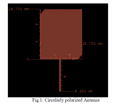
| Antenna Design: The designed circularly polarized truncated square patch antenna at 2.45 GHz is shown Fig.1. For simulation purpose FR4 has been taken as substrate whose dielectric constant and thickness are 4.4 and 1.6mm respectively. The simulation has been performed using Agilent ADS Momentum software. For calculation of the side length of the square patch, used equation is mentioned below: |
 |
| Where, dielectric constant of the substrate is εr. |
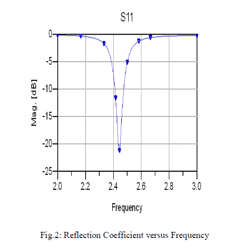
| Simulation results of the circularly polarized antenna are shown in Fig.2 and Fig.3. From Fig.2, at 2.45 GHz |
| reflection co-efficient is -21.28 dB which shows a good result. |
 |
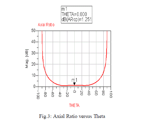
| From Fig.3, in the direction of maximum gain i.e. when theta is zero degree axial ratio is 1.251 dB which assures that antenna performs a good circular polarization characteristics at operating frequency 2.45 GHz. |
 |
| Fig.3 shows magnitude of axial ratio vs. Theta plot which ensures a good result of circular polarization. |
 |
| Rectifier Circuit Design: The schematic diagram of the rectifier circuit which has been designed using Agilent ADS is shown in Fig.4. |
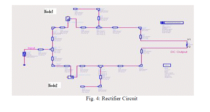 |
| The rectifier circuit contains two HSMS2860 commercial Schottky diodes in a SOT23 package. These diodes have forward and breakdown voltages of 0.3 and 7 V respectively. The zero bias junction capacitance Cj0 is 0.18 pF and the series resistance Rs is 5 V. |
| The rectifying circuit is based on a coupling between the Momentum and harmonic balance simulation of Agilent ADS. In a first time, the distributed part of the circuit is simulated using Momentum, and the S-parameters matrix is extracted. After that, HB uses this matrix and the packaged lumped element’s models to accurately simulate the full circuit. |
| The simulated input impedance of the diode is 95 - j200 Ω at 2.45 GHz and 10 dBm input RF power. All the lines have characteristic impedance () of 76 Ω except at the input of the circuit where a 81 Ω micro strip line is used as the feeding line from the antenna side. These lines are chosen to match the input of the rectifier with the truncated square patch antenna. |
| The DC voltage is obtained by measuring the voltage difference between V1 and V2 across the 1500 Ω resistor load, without reference to the RF ground plane. Therefore, there is no need for any via-holes. The 2.45 GHz power yields from the antenna is split into two separated equivalent RF components, which propagate in phase on both symmetrical and parallel 81 Ω micro strip lines towards diodes D1 and D2. The rectifier circuit also contains two quarter wavelength open stubs that act as RF short circuits to isolate RF and dc components and remove unwanted harmonics at input and output [6], [7]. |
III. RESULT AND DISCUSSION |
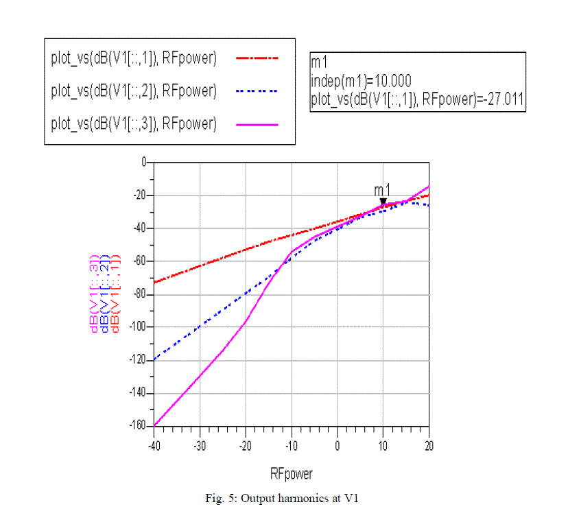
| Fig. 5 shows three harmonics (2.45 GHz, 4.90 GHz and 7.35 GHz) level at V1 which are significantly reduced (<-27 dB) at 10 dBm received input RF power. |
 |
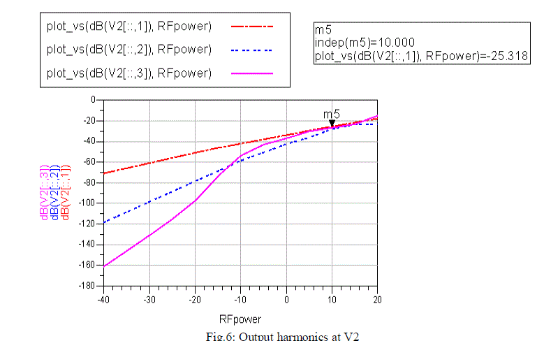
| Fig 6 shows three harmonics (2.45 GHz, 4.90 GHz and 7.35 GHz) level at V2 which are also significantly reduced (<-26 dB)at 10 dBm received input RF power. |
 |
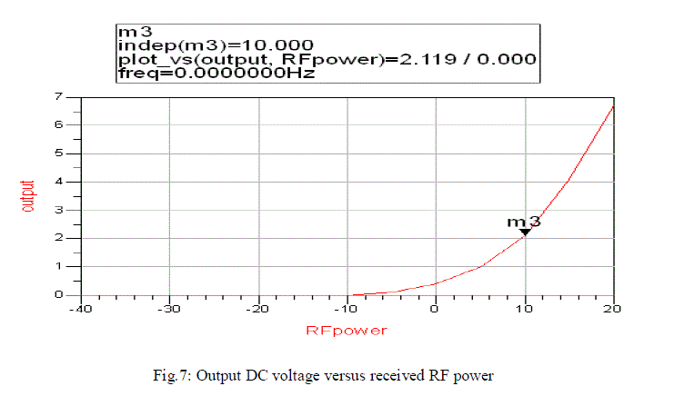
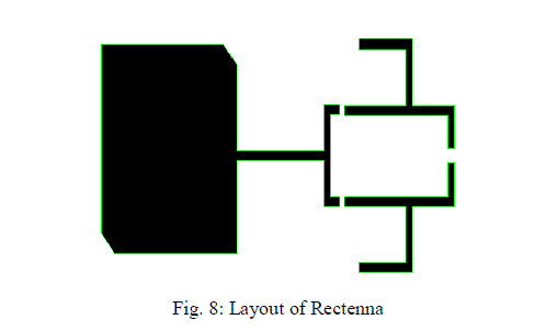
| Fig. 7 shows output DC voltage, which is volt at 10 dBm received input RF power. Fig. 8 shows layout of the rectenna. |
 |
| Fig. 7 shows layout of the complete rectenna. |
 |
| A 2.45 GHz circularly polarized rectenna has been simulated using Agilent ADS. It gives volt output DC voltage at 10 dBm received input RF power. Harmonics levels at output are significantly reduced. Work is on progress to practically validate this design. |
References |
|