ISSN ONLINE(2278-8875) PRINT (2320-3765)
ISSN ONLINE(2278-8875) PRINT (2320-3765)
Harika Sadasivuni1, Porselvi Thayumanavan1, Subramanian AN2
|
| Related article at Pubmed, Scholar Google |
Visit for more related articles at International Journal of Advanced Research in Electrical, Electronics and Instrumentation Engineering
In this paper, the design of a deck based power converter for powering thruster of a remotely operated underwater vehicle is presented. The variable thruster is mechanically powered with a Brushless DC motor. The power converter has to maintain a constant voltage of 300 V DC irrespective of the maneuvering speed. The power converter consists of three main parts viz., Three phase diode rectifier to convert input AC to DC, Buck converter to step-down the DC according to the load requirement and a microcontroller for varying the duty ratio using PWM. An Insulated Gate Bipolar Transistor (IGBT) is used as a switch. The output voltage is maintained at 300 V DC by increasing or decreasing the duty ratio. Switching techniques employed is based on the measured buck output voltage and current for a given cable resistance which is adjusted from sensed correction to keep constant 300V DC output at the equipment. Index Terms—Power Converter, Remotely Operated Vehicle, 5 kW Regulated Power Supply.
Keywords |
| Power Converter, Remotely Operated Vehicle, 5 kW Regulated Power Supply. |
I.INTRODUCTION |
| Advancements in the field of marine operations and support activities have necessitated the development of work class Remotely Operated Vehicles (ROV). The automation of such devices demands for the need of sophisticated power sources. The transmission is made through umbilical cable along with communication systems. The deeper the technology reaches, the longer the cables are supposed to carry the power. Consequently, current flows through resistance of the cable that manifests into higher transmission losses. Handling bulky objects in shallow waters necessitates complex design, owing to the randomness of the hydrodynamics. Minimalistic equipment which is absolutely necessary at such reach is only integrated along with the vehicle. Given the uncertainty in such environment, I2R losses are justified by the compact sized vehicle. |
| The deck based power supply for the ROV is designed using a two stage converter. In the first stage, the 415 V AC is converted to 580 V DC. Later the 580 V DC is step down to required voltage using closed loop control of the buck converter and transmitted through 550 m long umbilical cable of resistance 6 Ω / km. The required voltage at the output of the buck converter has to compensate the transmission losses in addition to the 300 V required by the motor load. |
| The closed loop control of the buck converter is achieved using a microcontroller by estimating the voltage drop across the 550 m long cable sensed by current flowing through it and then by calculating the required voltage to be generated at the buck converter output. |
II. COMPONENTS OF THE POWER CONVERTER |
| Three Phase Diode Rectifier |
| Buck Converter |
| Microcontroller |
III. DESIGN OF THREE PHASE DIODE RECTIFIER |
| i. Input to the diode bridge rectifier |
| 415V, 50Hz AC Supply |
| ii. Output of the diode bridge rectifier |
| V0 = (3* Vml) / π = 560V DC Where Vml = √2 * 415V |
| iii. Peak Diode Current |
| Iml = Vml/R = 88.92Amp |
| iv. Peak Inverse Voltage |
| Vml = 586.89V |
| v. Diode Rating |
| For a Safety factor = 2, |
| Current rating is 178Amp |
| Voltage Rating is 1174V |
IV. DESIGN OF BUCK CONVERTER |
| i. Input to the buck converter |
| = output of the rectifier = 560V |
| As per IEC standards, |
| ii. Voltage Ripple = 5% |
| ΔV = 300*5/100=15V |
| iii. Current Ripple = 5% |
| ΔI = 16.66*5/100 = 0.83Amp |
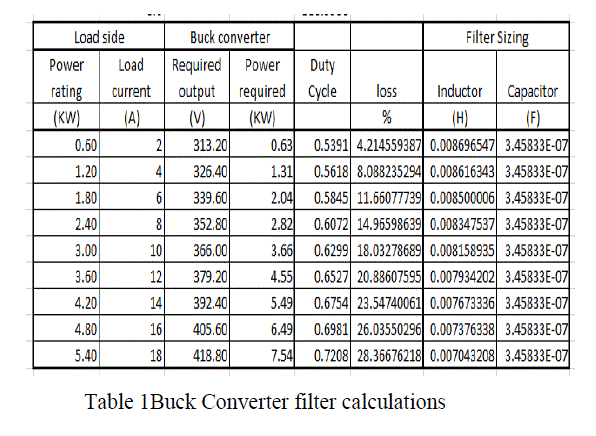
| Buck Converter filter values are obtained by taking the average value of the inductor and capacitor values for different loads as shown in Table 1. |
| iv. Inductance |
| L = [∂*(1- ∂)*Vs]/ (fs*ΔI) = 8mH |
| v. Capacitance |
| C = ∂*(1- ∂)*Vs/(8*L* ΔV*fs 2 ) =3.2μF |
V. MICROCONTROLLER OPERATION |
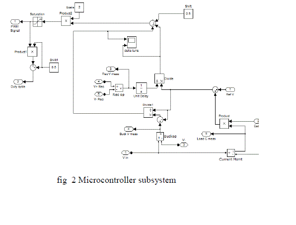
| The simulation subsystem of microcontroller is shown in fig 2. The error correction signal for PWM generation is calculated as follows. |
| Firstly, the required voltage at the buck converter output is calculated as voltage drop across the cable plus load requirement of 300V DC |
| Then the Input1, Input2 and Input3 are calculated as shown below. |
| Operation of Microcontroller |
| Input1=Buck output Voltage – Buck required output Voltage)/Buck required output Voltage |
| Input2 =Buck required output Voltage/Buck Input Voltage |
| \Input3=(Input2 – Input1-0.5)*2 |
VI.SIMULATION |
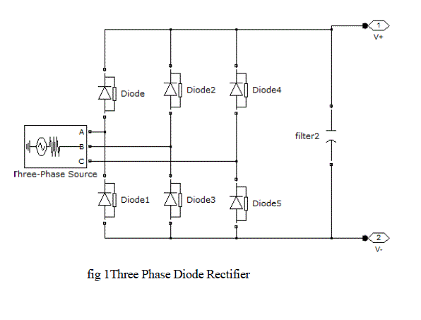
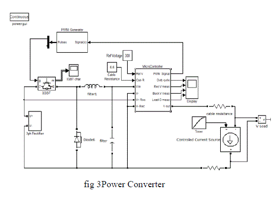
| The simulation was carried out using MATLAB SIMULINK software. The simulink models of three phase diode rectifier, microcontroller and power converter are shown in fig 1,2 and 3. |
 |
 |
 |
 |
VII. SIMULATION RESULTS |
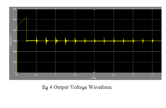 |
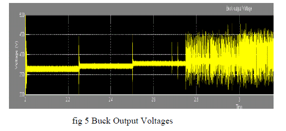 |
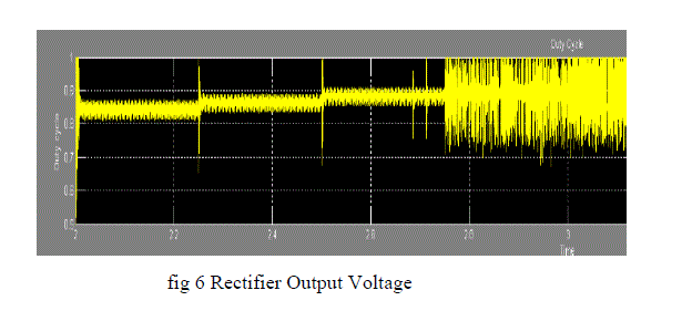 |
VIII. ABBREVATIONS AND ACRONYMS` |
| Vo = Output DC Voltage |
| Vml = Maximum value of line voltage |
| Iml = Maximum value of the line current |
| R = Load Resistance |
| ∂ = Duty Ratio |
| Vs = Input Voltage of Buck Converter |
| fs = Switching Frequency |
References |
|