ISSN ONLINE(2278-8875) PRINT (2320-3765)
ISSN ONLINE(2278-8875) PRINT (2320-3765)
Dharam Dutta1, Souvik Ganguli2,
|
| Related article at Pubmed, Scholar Google |
Visit for more related articles at International Journal of Advanced Research in Electrical, Electronics and Instrumentation Engineering
The design of a 60 kW bidirectional DC-DC converter is addressed in this paper. The paper also discusses the operation and role of dc-dc converter in Electric Vehicle (EV) and Hybrid Electric Vehicle (HEV). Various circuits and their analysis are done to review the operation and design of converter. Results show that at 20Hz operation converter efficiency is better when ETD49 shape is used rather than EC70. However efficiencies are greater with ferrite materials rather than iron powder.
Keywords |
| Hybrid Electric Vehicles (HEV), Bidirectional dc-dc converter, boost and buck operation, power losses, EC70, ETD49, IGBT. |
I. INTRODUCTION |
| In recent years more and more countries vehicles industry showed interest towards HEV. There is a huge investment in internal combustion engine powered vehicles. So the transition to an all-electric mobile fleet appears to be desirable, but due to several keys technologies and business issues, it is restricted. Hybrid vehicles have several advantages over conventional vehicles and there are few models available in the market. From power electronics point of view, there has to be power chains in which two power circuits has to be developed .For hybrid vehicles, the batteries and the dc drive link may be at different voltage Batteries are at low voltage levels and dc link may be at high voltage levels to have higher efficiency on the motor. Therefore, a good interfacing between the batteries and the driveâÃâ¬ÃŸs dc link is essential. This interface handles power flow in between battery to motor, motor to battery, external genset to battery, and grid to battery. The inverter drives the motor and the DC/DC converter between the battery and the high voltage bus. The designed DC/DC converter should be bi-directional so that the energy can flow from the battery to the DC link and from DC link to the battery. There is a tremendous effort in past decade to shift from conventional gasoline engines to hybrid electric vehicles. Factor responsible is the improvement in performance, size, cost of power electronics circuits. Designed converters maintains a constant DC link voltage when it is in motoring mode of operation and energy flow from DC link to battery when it is in generating mode of operation. Different multiple-input power electronic converter Topologies have been proposed to interface traction drive requirements with on-board energy sources mainly based on (i) pulse width modulation (PWM) dc-dc converter for high/low voltage sources, (ii) flux additivity, and (iii) converters for energy storage units including ultra-capacitor banks. Chen in [6] proposed a converter topology having two input voltages and a output voltage .Two dc sources are used in parallel using a coupled transformer. to utilise the double input PWM dc-dc converter in high/low voltage sources .In order to implement the double-input PWM dc-dc converter for high/low voltage sources . Input dc are combined in magnetic form by adding all the produced magnetic flux in magnetic core of coupled transformer .to combine two current fed full bridge dc/dc converters known as the concept of magnetic flux additivity [9]. |
| Two or more sources of power are there in hybrid electric vehicles. Sources can be battery, flywheel, etc. sources of power can be an engine, a fuel cell, a battery, an ultra-capacitor. Two or more power sources can be used depending on the type of configuration. Electric motor and internal combustion engine are combined in such a way that most desirable characteristics can be used to minimise pollution. Classification of HEV can be done as series and parallel. In series hybrid vehicles, generator is driven by engine, and in turn, power the electric motor. The engine and the electric motor are coupled in a parallel hybrid. A series hybrid vehicle can offers lower fuel consumption in a city during frequent start /stop operation making its ICE to operate at its highest efficiency. In the highway driving vehicles, a parallel hybrid vehicle can have lower fuel consumption in which the ICE is at the highest efficient point with its constant speed. Depending on the objective and role to be performed by engine and motors, hybrid vehicles may be mild hybrid, power hybrid and energy hybrid. |
II. DC-DC CONVERTER AND HEV |
| A. Bidirectional dc-dc converter |
| Buck and Boost converter do not have bidirectional power flow capability. Reverse current flow is not possible due to presence of diodes in their structures. Thus, a unidirectional dc dc converter can be turned into diodes by replacing diodes with controllable switch. When the energy storage is placed on the high voltage side, it is of buck type. And similarly boost type dc-dc converter is to have energy storage on low voltage side. Switch cell should carry the current in both directions to realize the double sided power flow in bidirectional dc-dc converters .Generally IGBT or MOSFET are used in parallel with diode. |
| B. The Hybrid Electrical Vehicle |
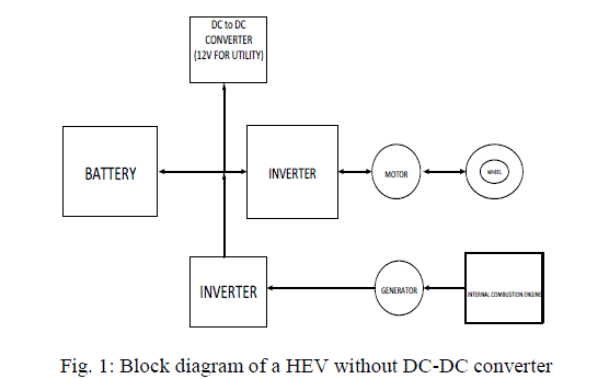 |
| In Figure1 shown the block diagram of a HEV with a battery directly connected to the inverter and further connected to the electric motor, and in the opposite direction power is transferred from Load (wheel-motor) to battery through inverter. In the other way the power comes from the generator to the inverter which is connected to the ICE. |
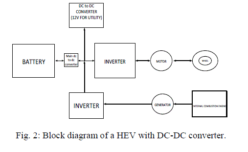
| Figure 2 shows the block diagram of a HEV with DC-DC converter. The DC-DC converter in a HEV is used to maintain a constant dc link voltage and to step up and step down the voltage as shown. |
 |
| C. Circuit description and operation |
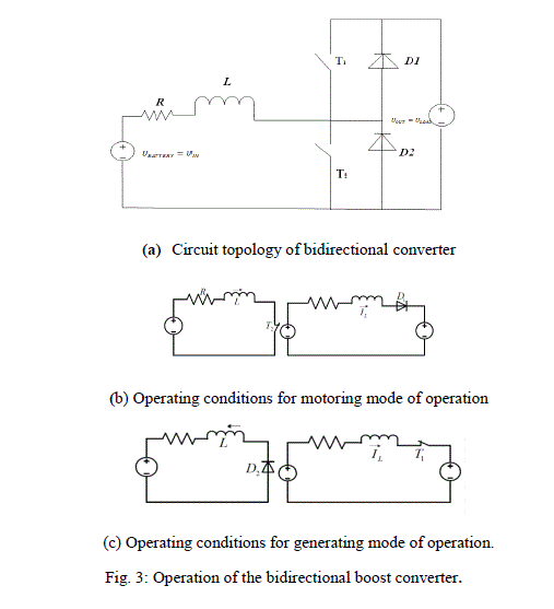
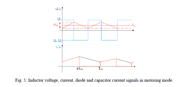
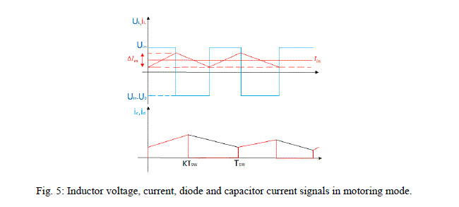
| Generally two bidirectional DC-DC converters in HEV. One of them is a high-power converter that links the hybrid power train battery at a lower voltage with the high voltage DC bus. A second low-power converter links the hybrid battery with the low voltage auxiliary battery [1].The operating principle of the DC-DC converter is shown in Figures 3.a-c. |
 |
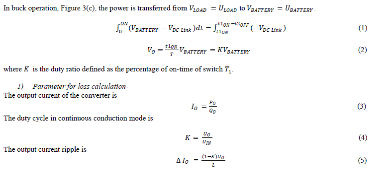
| D. Generating mode |
 |
 |
 |
 |
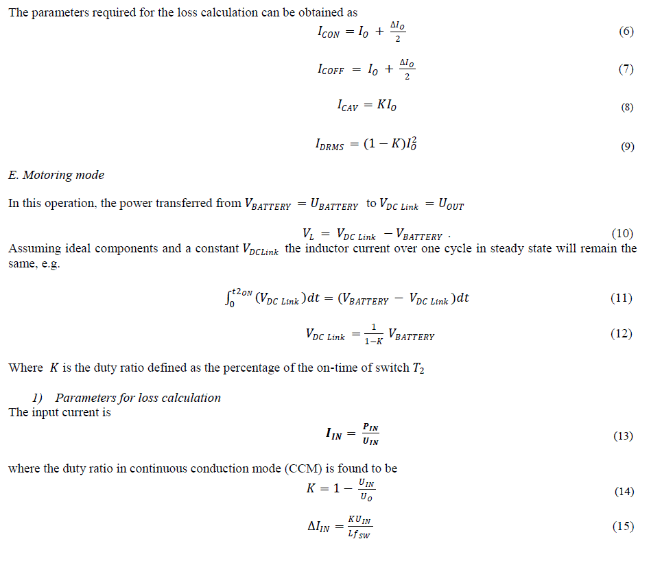
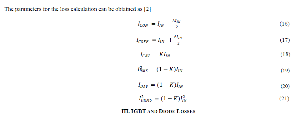
| The parameters for the loss calculation can be obtained as [2] |
 |
III. IGBT AND DIODE LOSSES |
| The IGBT and diode power losses as well as the power losses in any semiconductor component can be divided in three groups [2] a) Conduction losses (Pcunduction) b) Switching losses (Psw) c) Blocking leakage losses usually neglected Therefore |
| Psemicunductor=Pcunduction+Psw (22) |
IV. INDUCTOR DESIGN EQUATIONS |
| Inductors are to be designed for these power levels and it is therefore now designed for this particular application [4]. |
| A. Design of the inductor |
| 1) Parameters: |
 |
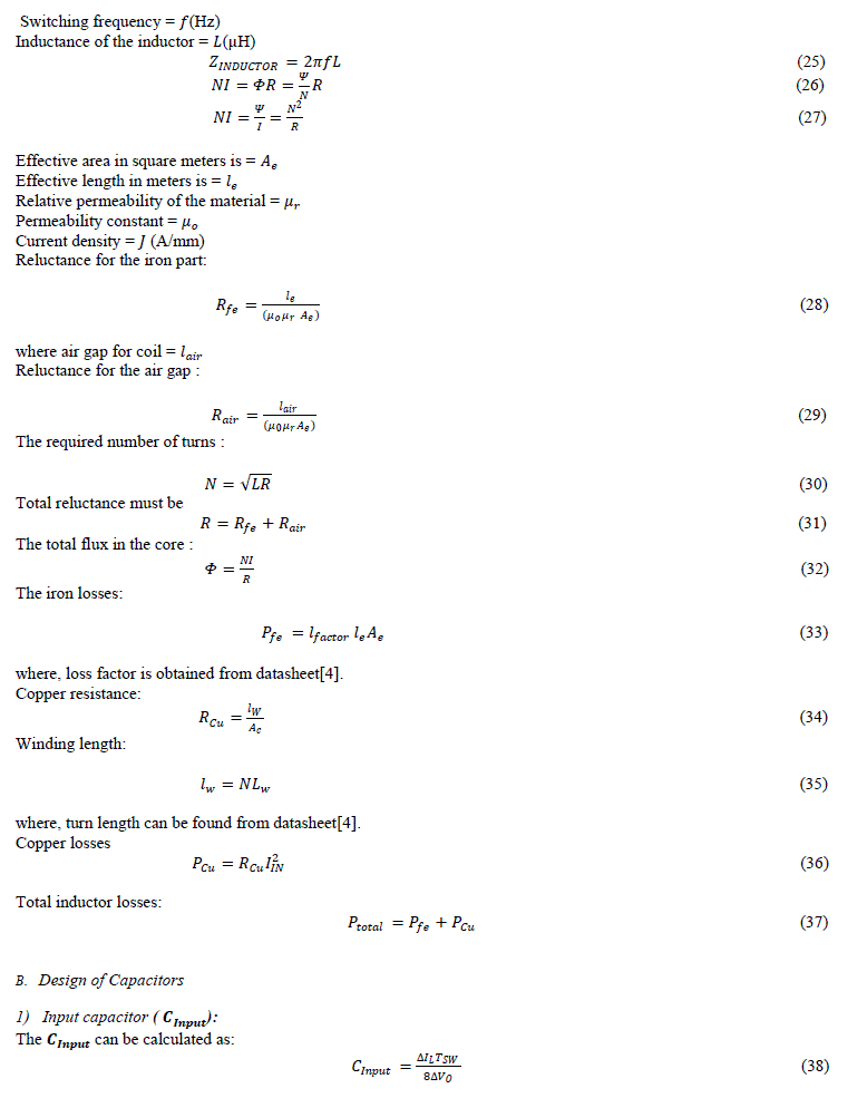
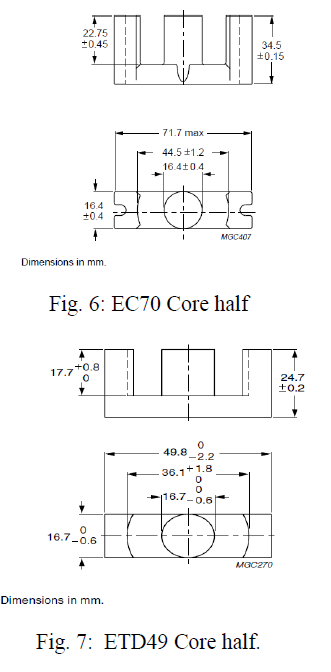
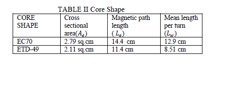
| 2) Core material, shape and size |
 |
 |
| For inductor design |
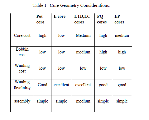
| 1) Core shapes: Different types of core shapes can be taken into application for inductor design. These may be pot types, EC cores, EE cores, ETD cores, etc. Inductor core design can be generally done by EC and ETD cores. Ferrite core different geometry considerations can be tabulated as follows |
 |
 |
 |
| 2) Core Materials: |
| Ferrite: |
| Relative permeability = 5000 |
| Various compositions -iron oxides, |
| Fe-Ni-Mn oxides |
| Important properties- Relative permeability ranges from 2-15000. |
| Resistivity very large (insulator) |
| Bs = 0.3 T (T = tesla). |
| Iron powder : |
| Relative permeability = 71 |
| Iron-based alloys |
| • Various compositions |
| Fe-Si(few percent Si). |
| Fe-Cr-Mn |
| • Important properties- |
| Relative permeability ranges from 0 - 75. |
| Resistivity = (10 - 100) resistivity of Cu. |
| Bs = 1 - 1.8 T (T = tesla). |
| Powdered iron can be sintered into various core. |
| Powdered iron cores have larger effective resistivity |
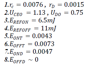
| Parameters used for loss calculations [24]: |
 |
VI. RESULTS |
| Results for the analysis can be tabulated as follows |
 |
VII. CONCLUSION |
| Bidirectional dc-dc converter is designed with two type of cores namely EC70 and ETD49.Analysis shows that at 20Hz operation converter efficiency is better when ETD49 shape is used rather than EC70. However efficiencies are greater with ferrite materials rather than iron powder. Designed dc dc converter can further be analysed by state space averaging technique in which we can further estimate the stability of converter designed. Control to output impedance, output impedance and susceptibility can be investigated to check the performance of this designed converter. |
References |
|