ISSN ONLINE(2278-8875) PRINT (2320-3765)
ISSN ONLINE(2278-8875) PRINT (2320-3765)
Salice Peter1, Naveen N M2, Nidheesh M N2, SwethaAnnu James2, Seril Joseph2
|
| Related article at Pubmed, Scholar Google |
Visit for more related articles at International Journal of Advanced Research in Electrical, Electronics and Instrumentation Engineering
Tachometer is used to measure speed of motor or shaft or propeller. This tachometer is designed using ATMega16 micro-controller. It can measure time interval with better accuracy. Attractive feature of this is it measures speed without any physical contact with shaft or motor. It shows RPS speed on LCD and Tachometer setting can be changed from simple push buttons. It uses low cost infrared transmitter-receiver pair for sensing propellers. It can measure RPS speed up to the desired value, depends on the speed of the motor
Keywords |
| Tachometer, ATMEGA16 microcontroller, infrared module, dc motor |
I. INTRODUCTION |
| Speed of a motor is one of the important factors to be considered while dealing with dc motors. It determines the power drawn by the motor, efficiency, loading, etc. Also if the machine runs above the rated speed, it might damage or even burn off the machine. So knowing about the speed of a machine is inevitable in order to calculate or control the speed. |
| Contact less tachometer is a device used to measure speed of a motor by counting the number of rotations per second of a rotating shaft using micro controller. As the name indicates, it can very accurately measure the rotational speed of a shaft without even touching it. This is interesting because making direct contact with the shaft is not an option, and will reduce the speed of the shaft giving faulty readings. This can also be employed to measure the speed of motors which are at unreachable places. |
| This device is built on a microcontroller - ATmega16, speed is detected using the IR transmitter and receiver pair, readings are displayed using a 16x2 LCD display and the speed limit is indicated by an LED and a buzzer. It works on the principle that the number of times the IR receiver-transmitter circuit is cut and re-established in a second gives the number of rotations per second. The value is displayed on the LCD display. The screen is refreshed after each second. When the speed of the motor is above a fixed value, a buzzer is alarmed and an LED indication is given. |
II. IR TRANSCEIVER |
| IR transceiver is used here for determining the number of rotations of the motor shaft per second. This is done by counting the number of times the slot comes in line of sight with the transmitter receiver pair. |
| A. Transmitter |
| The Infrared Emitting Diode (IR333/H0/L10) is a high intensity diode, molded in a blue transparent package. The device is spectrally matched with phototransistor, photodiode and IR receiver module. It finds applications in IR remote control units, smoke detectors, free air transmission systems etc. |
| B. Receiver |
| The IR LED converts the incident IR radiations to an equivalent electric current which when passed through a resistor results in a certain amount of voltage drop. This value of voltage will depend upon the intensity of incident IR radiations or in other words, the distance between IR transmitter and receiver. The receiver is connected in reverse bias in the circuit. The IR rays emitted by the transmitter get reflected back after hitting the target. Receiver coverts this received radiations to a corresponding electric current. |
III. WORKING AND CIRCUIT OPERATION |
| Contact less tachometer is a device used to measure speed of a motor by counting the number of rotations per second of a rotating shaft using micro controller. As the name indicates, it can very accurately measure the rotational speed of a shaft without even touching it. |
| A. Circuit operation |
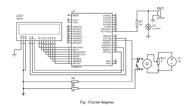
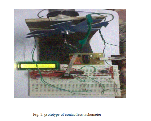
| The contactless tachometer works on the basis of the infrared transmitter receiver circuit. In the circuit we have placed the IR transmitter and receiver at either side of the DC motor such that both are in line. The shaft of the DC motor was fitted with a cardboard with slots such that the IR transmitter and receiver can make connection through the slots. As the motor runs, the IR transmitter fitted with the cardboard also rotates with it. The slot that made on the cardboard and the IR receiver are in line with the IR circuit. Thus, connection between the IR transceiver closed at each slots and current passes through the circuit. This current makes a voltage drop in the resistors connected in the circuit. The voltage across the resistor connected in series with the receiver is transferred to the second pin of port D of the Microcontroller ATmega16. |
 |
| The microcontroller ATmega16 is programmed such that each time the voltage in the pin of microcontroller changes from zero to a high value, it initiates a timer interrupt. The interrupt counts the number of times the voltage variation occurs in the resistor in series with the receiver and sends the value to the LCD display every second. Another timer resets the counter after each second. So we get the number of rotations per second of the motor shaft. |
 |
| The setup provides a LED and a buzzer to make warning or indication of some fixed rated speed of the motor. The LED and the buzzer connect to the microcontroller which monitors the speed of the motor. Such a setup needs a variable potentiometer to be connected across the supply of the motor and thereby the speed of the motor can be varied to an extent. By varying the supply using the potentiometer, the speed of the motor varies and when the speed reaches or exceeds the fixed rated speed, the LED will glow simultaneously the buzzer beeps |
| The Microcontroller is programmed such that when the output of the counter attains a value above a fixed value (in this paper the value is fixed at 29 rps), it sends a high signal to its MSB (7th pin) of port C which is connected in series with an LED and a buzzer. Hence we can get an alert whenever the speed of the motor goes above a fixed value. In real time applications an IR transceiver module can be used instead of the transmitter receiver pair. A receiver is placed at one point on the motor so that each time the center. IR rays emitted by the transmitter and hits the receiver. Each time this happens a counter is initiated. |
IV. CONCLUSION |
| The circuit of our paper was designed and implemented. The speed of the motor is displayed on the LCD display every second. When the speed of the motor became more than 29 rps, the LED glowed and the buzzer alarmed. When the speed of the motor again comes back to less than 29 rps, the LED and the buzzer stopped. |
References |
|