Now a day due to vast change in industrial trend, pumping applications are switching over to high head requirements. At the same time industry demands for pump with simple construction, easy for maintenance with lowest possible price. For such applications multistage pump is the only conventional available option which has its own limitations like difficulties in maintenance, lesser efficiencies, more number of parts etc. However end suction pumps are easier for maintenance on account of its construction, are having comparatively higher efficiencies because of lower flow disturbances and are having less number of parts. If an end suction pump is forced to operate at higher speed, (2900 rpm and above) then the conventional end suction pumps can generate higher heads. The high speed end suction pumps will prove as a good replacement of medium pressure multistage pump.
Keywords |
| End suction pump, high head, design of pump, volute casing, pump performance |
INTRODUCTION |
| Pump is a mechanical device used to transfer liquid from one location to another location. When impeller rotates in
the casing it accelerates the fluid through its vanes and kinetic energy gets transferred from impeller to the fluid. In
the pump casing the kinetic energy of fluid converted in to pressure energy. |
| Though the working principal of centrifugal pump is very simple, it has a wide application range of applications from
small monoblock pumps with very less discharge to large vertical turbine or concrete volute pumps with thousands
litres of discharge per second. Pumps are used for variety of pumping applications like water, acids, alkalis, brines,
organic compounds etc. |
| When there is requirement of pump with high head, normally multistage pumps are offered. Function of a multi stage
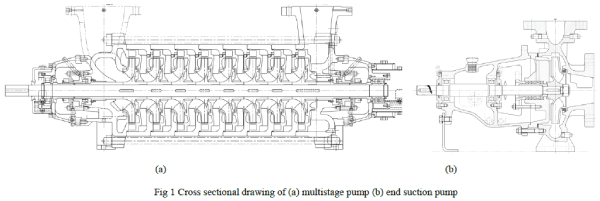
pump is similar to two or more number of pumps arranged in series. Fig 1 (a) shows sectional views of multistage
pump. In multistage pumps numbers of impellers are arranged on single shaft. Each stage contains impeller, stage
casing and diffuser. Each stage develops certain amount of head and numbers of stages are decided by dividing total
head required with head developed per stage. For multistage pumps the total assembly is complicated and more
number of parts with high machining accuracy is required as variation in dimension gets multiplied by number of
stages. Also skilled labour required for pump assembly. |
| While searching out solution on these issues, it was found that only single stage end suction pump can overcome these
problems but not capable of developing high heads. One more interesting thing triggered out that the high head
requirement can be met by increasing driver speed as head developed by pump is proportional to the square of speed.
If we increase the speed of pumps from 1500 to 3000 rpm the head obtained is approximately will be 4 times of the
presently available head. The concept of doubling the speed considered and decided to implement it practically. All
the components are newly designed to suit 3000 rpm as head becomes 4 times higher and torque and power becomes
8 times higher. |
| Fig 1(b) shows sectional view of end suction pump if we see fig1(a) and 1(b) we can say that end suction pump is
very simple in construction as compared with multistage pump and the main challenge is to design and develop end
suction pump to get desired output with satisfactory performance of pump. |
 |
| MATERIALS AND METHODS |
| The concept of doubling speed looks simple but a lot of technical aspects are required to be considered while doubling
the speed. Since speed is doubled the tip or peripheral speed of impeller increased to 63.1m/s. For satisfactory working
impeller, stainless is selected as impeller material. In multistage pumps initial stages are under low working pressures
as pressure gets added step by step. However since this is single stage pump maximum allowable working pressure is
considered as design criteria and accordingly SG Iron or stainless is decided as minimum material for pump casing.
Based on earlier studies of failure analysis, stainless shaft grade SS316 is selected for further calculations as this
material has good mechanical strength with high corrosion resistance. |
| Pump casing and impeller are cast components their manufacturing mythologies are as per standard procedure followed
in pump industry i.e. deign, preparation of 3D drawing, pattern and core box manufacturing, preparation of moulds,
metal pouring and machining of casting etc. |
DEVELOPMENT OF HIGH SPEED PUMP |
| For development of high speed pump decided to select end suction pump whose mechanical design is suitable upto
1500 rpm. It was decided to redesign the pump in such a way that the pump can run at 3000rpm. This is very important
aspect as due doubling the speed pump flow gets doubled, head developed by pump becomes 4 times higher and power
requirement becomes 8 times higher. |
| Following steps followed. |
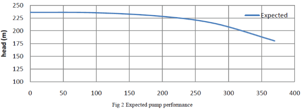
| 1. Expected flow range, head value etc. decided as Flow between 200 to 350m3/hr and head 205m or above.
These inputs are based on current market scenario where multistage pumps are used for 200m and above head
requirements. |
2. New pump’s specific speed calculated using formula,  Existing 4” end suction model finalised for
redesign as specific speed of this 4” pump is close to new pump’s specific speed. Expected performance calculated
using affinity lawand curve plotted. Following figure shows the expected performance of pump. Existing 4” end suction model finalised for
redesign as specific speed of this 4” pump is close to new pump’s specific speed. Expected performance calculated
using affinity lawand curve plotted. Following figure shows the expected performance of pump. |
 |
| 3. This is end suction pump and axial thrust exists due to unsymmetrical shape of impeller. Axial thrust
calculated using formula mentioned in HI 1.3 standard and its value is FA = 9850.84232 N |
| 4. Radial thrust(FR) acts on impeller. As liquid flows through volute area, velocity head gets converted to
pressure head and exerts pressure on impeller peripheral area and volute wall. |
| FR= KR × H × ρ × g × D2 × B |
| Where, KR= Thrust factor, |
| H = Head developed by pump = 205m |
| ρ = density of liquid = 1060Kg/m3 |
| g = Gravitational constant (9.81 m/s2) |
| D2 = Diameter of impeller = 0.409m |
| B = Width of impeller= 0.015m |
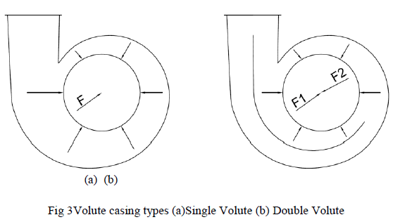
| Fig 3(a) is single volute design it is unsymmetrical but easy for manufacturing, there are chances of higher radial
thrust on impeller. Fig 3(b) is double volute design it is more symmetrical than single volute due to this major part of
thrust acting on impeller get balanced but more foundry skill involved in pattern making and manufacturing. |
 |
| Radial thrust factor calculated for single volute casing. Thrust value is considerably high i.e. 1830.92N. This resulted
into higher bearing sizes and shaft diameter. To optimize the design, calculations carried out for double volute
casings.Due to symmetrical design of double volute, thrust factor KRis small. Thrust coming on impeller is 588.51N.
This is considerably low as compared with single volute. So double volute design finalised. |
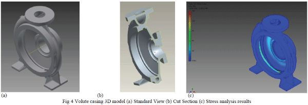
| 5. Using pressure vessel analogy pump casing is designed. 3D model of the casing is prepared.Fig 4(a) and (b)
shows 3D model of casing and cut sectional view of casing respectively. After preparation of 3D model, stress
analysis of casing carried out by applying pressure in inner part of casing. Stress analysis carried out in Autodesk
Inventor software. Fig 4(c) shows stress analysis results. |
 |
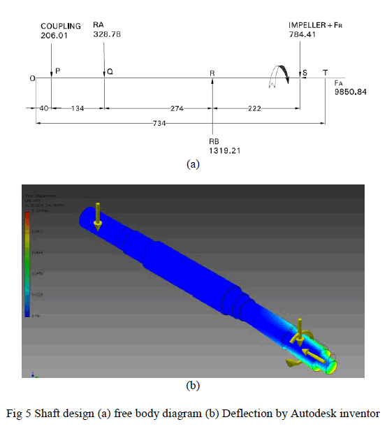
6. Shaft Design – Refer Fig 5(a). Free body diagram of shaft is drawn. Shear force and bending moment values
are calculated. Based on these shaft design is done. Maximum deflection of shaft is calculated using
formulay  Deflection values are cross checked using Autodesk Inventor (Refer Fig 5(b)). Deflection values are cross checked using Autodesk Inventor (Refer Fig 5(b)). |
 |
| 7. Critical speed of Pump – For this newly designed pump critical speed calculated using formula, |
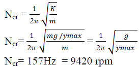 |
| The newly designed high speed pump speed(N) is 3000RPM. As per guidelines from various pump handbooks and
vibration related literatures the operating speed should not close to critical speed, it should be lesser than 0.8Ncr or more than 1.3 times critical speed (Ncr). This helps to avid abnormal vibrations due to resonance. For this newly
designed pump, speed (N) is far away from resonance speed band. |
| 8. Using all these calculation results, detailed design of pump is carried out. Major component’s designs
validated by carrying stress analysis. The stress analysis and design calculation results found close to each other. |
MANUFACTURING AND EXPERIMENTAL TESTING |
| 1. This end suction pump manufactured using various process followed in pump manufacturing industry. |
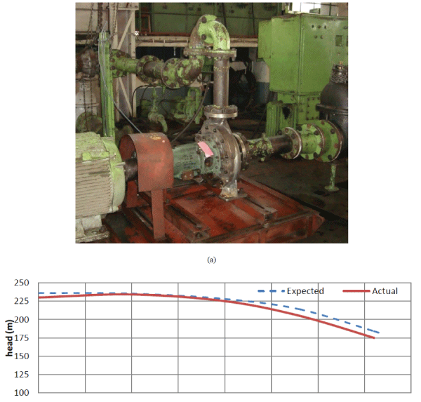
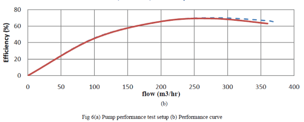
| 2. The pump tested in pump testing laboratory. Fig 6(a) shows pump testing setup at testing laboratory.
Parameters like head, power, bearing temperatures vibrations etc. measured for various flows. Finally performance
curve of newly designed curve established. Fig 6(b) is performance curve of the newly designed pump. |
 |
 |
CONCLUSION |
| The newly designed high speed high head end suction pump achieved the required duties mentioned. The overall
hydraulic performance of pump is very close to expected values. The values of bearing temperatures, noise and
vibration levels observed during performance are well within acceptable limits. This type of design made the pump
compact, easy to assemble, less number of parts and economical as compared to conventional multistage pump. Double
volute construction reduces the total radial load on the rotating unit. It reduces the shaft and bearing size as compare to
conventional pump.For the future growth expected in process sectorthis development of high head high speed process
pump has given the competent solution.In nutshell the high speed end suction pumps will prove as a good replacement
of medium pressure multistage pump. |
References |
- R.W. Fuller, J.Q. Ehrgott Jr., W.F. Heard, S.D. Robert, R.D. Stinson, K. Solanki, M.F. Horstemeyer, âÃâ¬ÃÅFailure analysis of AISI 304 stainlesssteel shaftâÃâ¬ÃÂ, Engineering Failure Analysis, Vol.15, Issue 7, pp.835âÃâ¬Ãâ846, 2008.
- F. Berndta, A. van Bennekomb, âÃâ¬ÃÅPump shaft failures - a compendium of case studiesâÃâ¬ÃÂ, Engineering Failure Analysis, Vol. 8, pp.135-144, 2001
- J. Stepanoff, âÃâ¬ÃÅCentrifugal and Axial flow pumps - Theory, Design & ApplicationâÃâ¬ÃÂ, John Wiley and Sons âÃâ¬Ãâ 2nd edition, 1953.
- Val S. Lobanoff& Robert R. Ross, âÃâ¬ÃÅCentrifugal Pumps design and applicationâÃâ¬ÃÂ, Jaico publishing house âÃâ¬Ãâ 2nd edition, 1995.
- VB Bhandari, âÃâ¬ÃÅDesign of Machine ElementsâÃâ¬ÃÂ, Tata McGraw Hill Education private Limited, 2010.
- Igor J Karassik& Ray Cartor, âÃâ¬ÃÅCentrifugal pumpsâÃâ¬ÃÂ, Tata McGraw Hill Book Company, 1960.
- ANSI/HI 1.3 standard on Rotodynamic pumps for design and application, 2009.
- ANSI/API STANDARD 610, 11th editionâÃâ¬Ãâ Centrifugal Pumps for petroleum,Petrochemical and Natural GasIndustries, Sept 2010.
- ASTM A 351/A 351M - Standard Specification for Castings, Austenitic, Austenitic-Ferrite (Duplex), for Pressure-Containing Parts, 2013.
- General catalog SKF bearing, âÃâ¬ÃÅSKF GroupâÃâ¬ÃÂ, June 2008.
|