ISSN ONLINE(2278-8875) PRINT (2320-3765)
ISSN ONLINE(2278-8875) PRINT (2320-3765)
Subhrajyoti Modak1, Goutam Kumar Panda2 Pradip Kumar Saha3, Sankar Das4
|
| Related article at Pubmed, Scholar Google |
Visit for more related articles at International Journal of Advanced Research in Electrical, Electronics and Instrumentation Engineering
Fly-back converters have been widely used because of the irrelative simplicity and their excellent performance for multi output applications. They can save cost and volume compared with the other converters, especially in moderate low power applications..In a fly-back converter, a transformer is adopted to achieve galvanic isolation and energy storage. Modelling is done without parasitic as well as with parasitic components. A detailed analysis, simulation and different control strategy are conferred for Fly-back converter. To verify the design and modelling at primary stage, study of the converter in for input AC voltage220V at 50Hz and output DC voltage of 440V and 150W output power rating. Simulation result shows a little ripple in output of the converter in open loop. Finally in order to evaluate the system as well as response of the controller, Fly-back converter simulated using MATLAB.
Keywords |
| Voltage Mode Control, Current Mode Control, Discontinuous Conduction Mode, Metal Oxide Semiconductor Field Effect Transistor. |
I.INTRODUCTION |
| Fly-back converter is the most commonly used SMPS circuit for low output power applications where the output voltage needs to be isolated from the input main supply. The output power of fly-back type SMPS circuits may vary from few watts to less than 100 watts. The overall circuit topology of this converter is considerably simpler than other SMPS circuits. Input to the circuit is generally unregulated dc voltage obtained by rectifying the utility ac voltage followed by a simple capacitor filter. The circuit can offer single or multiple isolated output voltages and can operate over wide range of input voltage variation. In respect of energy-efficiency, fly-back power supplies are inferior to many other SMPS circuits but it’s simple topology and low cost makes it popular in low output power range. |
| The commonly used fly-back converter requires a single controllable switch like, MOSFET and the usual switching frequency is in the range of 100 kHz. A two-switch topology exists that offers better energy efficiency and less voltage stress across the switches but costs more and the circuit complexity also increases slightly. |
| Parameters such as switching frequency, distortion, losses, harmonic generation and speed of response are typical of the issues which must be considered when developing modulation strategies for a particular family of converters .The DC converter is a device which transforms AC to DC in[1].This device is also known as an AC to DC converter. A Chopper can be considered as a DC equivalent of an AC transformer with a convertible constant convertible in a continuous form. Like a transformer, the converter can be employed for stepwise increase or reduction of DC source voltage. The converters are widely used for the control of motor voltage in electric cars, ceiling elevators, mine excavation etc. Their specific features are the precise control of acceleration with high efficiency and fast dynamic response specially describe in [1]. |
| In [2] addresses a novel approach for designing and modelling of the isolate fly back converter. Modelling is done without parasitic as well as with parasitic components. A detailed analysis, simulation and different control strategy are conferred for fly back converter in continuous conduction mode (CCM). To verify the design and modelling at primary stage, study of the converter is practiced in CCM operation for input AC voltage 230V at 50Hz and output DC voltage of 5V and 50W output power rating using PSIM 6.0 software. Simulation result shows a little ripple in output of the converter in open loop. Finally in order to evaluate the system as well as response of the controller, fly back converter is simulated using MATLAB. This work, highlighting the modelling when the system have transformer and facilitate designers to go for it when they need one or more than one output for a given application up to 150W. |
| Electronic circuits which use integrated-circuits (IC) need a standard DC voltage of fixed magnitude which generally varies between -18 to +18 volts. In some electronic equipment one may need multiple output power supplies. For example, in a Personal Computer (PC) one may need ±5 volt and ±12 volt power supplies. These DC power supplies are generally provided from the standard power source i.e. AC voltage of 115V / 60Hz or 230V / 50Hz. For low output power applications the most preferred converter is fly back, the advantage of this converter is that the output state and the input main supply are completely isolated. Ref. [4] the circuit topology of fly back converter is simplest if we compare it with other SMPS circuits. The input given to the converter is generally unregulated dc voltage which is obtained by rectifying the ac voltage followed by a capacitor filter .Fly back converters use a transformer so that they can give single or multiple isolated output voltages. Ref. [5] but if we talk about energy efficiency (η), fly back converter is not good as compared with other SMPS circuits though its topology is very simple. Fly back can be operated in two different modes: |
| 1. Continuous conduction mode (CCM) |
| 2. Discontinuous conduction mode (DCM) |
| Ref. [1] if the application demands high voltage and low current output then DCM is mostly recommended. Meanwhile, CCM is recommended for low voltage and high current output applications in Ref [3]. Application are dealing with is low voltage and high current, so we have gone with CCM. This paper presents a simple methodology to design fly back converter with parasitic components. Although the impact of parasitic components may be negligible in low-power applications, but when the load resistance becomes considerably small, the effects of these parasitic elements cannot be ignored. Our approach starts with AC input of 230V which is converted to unregulated DC voltage and then supplied to the converter circuit. Ref. [6] fly back converter provides multiple isolated outputs and therefore it is the preferred topology for industrial applications. In this paper a basic concept of linear circuit is used to model the converter. Because of switching characteristics the converter is not a linear system and to apply linear control strategy the system (plant) must be a linear. So after some modulation the converter is modelled into a linear system for each of the switch options. |
| In Ref [7] designing of an optimized controller for isolated DC-DC Fly back converter for constant voltage applications. The Fly back converter can both step up and step-down the input voltage, while maintaining the same polarity and the same ground reference for the input and output. MOSFETs are used as a switching device in low power and high frequency switching applications. It may be noted that, as the turn-on and turn-off time of MOSFETs are lower as compared to other switching devices, which reduces the switching losses. High frequency operation of MOSFET reduced size of filters components. These converters are now being used for various applications, such as Switched Mode Power Supply (SMPS) etc. In Ref [7] attempts to present designing and tuning of Fly back converter for constant voltage output. |
 |
| Modes of Operation and Analysis: |
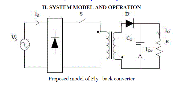
| In Fly-back converter power transformer is used for isolation between a primary side and a secondary side. There are basically two mode of operation. |
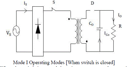
| Mode 1 (Switch is closed): When switch ‘S’ is on, the primary winding of the transformer gets connected to the input supply with its dotted end connected to the positive side. |
| At this time the diode ‘D’ connected in series with the secondary winding gets reverse biased due to the induced voltage in the secondary (dotted end potential being higher). Thus with the turning on of switch ‘S’, primary winding is able to carry current but current in the secondary winding is blocked due to the reverse biased diode. The flux established in the transformer core and linking the windings is entirely due to the primary winding current. |
 |
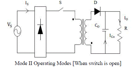
| Mode 2 (Switch is open): When the switch is opened the primary current and magnetic flux drops. The secondary voltage is positive, forward-biasing the diode, allowing current to flow from the transformer. The energy from the transformer core recharges the capacitor and supplies the load. |
 |
| Closed Loop Control: |
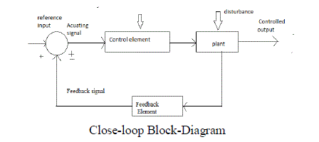
| This is also often termed as Automatic Control, Process Control, and Feedback Control etc. Here the controller objective is to provide such inputs to the plant such that the output y (t) follows the input r (t) as closely as possible, in value and over time. The structure of the common control loop with its constituent elements, namely the Controller, the Actuator, the Sensor and the Process itself is shown. In addition the signals that exist at various points of the system are also marked. These include the command (alternatively termed the set point or the reference signal); the exogenous inputs (disturbances, noise). The difficulties in achieving the performance objective is mainly due to the unavoidable disturbances due to load variation and other external factors, as well as sensor noise, the complexity, possible instability, uncertainty and variability in the plant dynamics, as well as limitations in actuator capabilities. Most industrial control loop command signals are piecewise constant signals that indicate desirable levels of process variables, such as temperature, pressure, flow, level etc., which ensure the quality of the product in Continuous Processes. In some cases, such as in case of motion control for machining, the command signal may be continuously varying according to the dimensions of the product. Therefore, here deviation of the output from the command signal results in degradation of product quality. It is for this reason that the choice of the feedback signals, that of the controller algorithm (such as, P, PI or PID), the choice of the control loop structure (normal feedback loop, cascade loop or feed forward) as well as choice of the controller gains is extremely important for industrial machines and processes. Typically the control configurations are well known for a given class of process however, the choice of controller gains have to be made from time to time, since the plant operating characteristics changes with time. This is generally called controller tuning. |
 |
III. SIMULATION AND RESULT DISCUSSION |
| Simulation of Fly-back converter for open loop control. This is the open loop simulation of the flyback converter circuit. The MATLAB simulation diagram is shown in figure and its voltage and current response is shown in figures which depicts peak to peak ripple voltage (ΔVO) is 440V. Since the design equations assume constant input voltage and constant load under steady state conditions, the variation of input voltage shall result in fluctuation in output Therefore, a closed loop controller is required with optimized parameters to suit the constant voltage output as per requirement of load. |
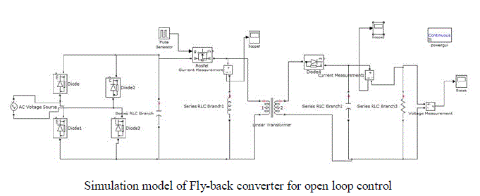 |
| The above figure shows the simulation diagram of the proposed flyback converter simulated in matlab software to verify the working of the proposed model. |
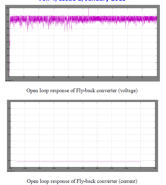 |
| Where the values of parameter are, input voltage [Vin] =220 volts, Output voltage [Vout] =440volt, Switching frequency=25 kHz, Inductor value=43.6mH, filter capacitor=135μF, Therefore output values shows, there are variations in output voltage, and fluctuation is more. In order to minimize the fluctuation we added a controller in closed loop. |
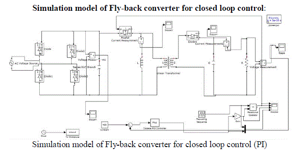 |
| The Simulink Schematic of fly-back converter with analog PI controller is shown in above Fig. The output voltage is sensed Vout and compared with the input voltage Vref. An error signal is produced which is processed through PI controller to generate a control voltage. The control voltage is used to feed to the PWM generator for control of switch. |
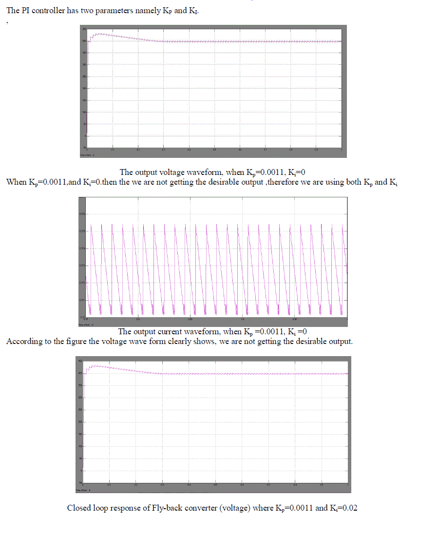
| The PI controller has two parameters namely KP and KI. |
 |
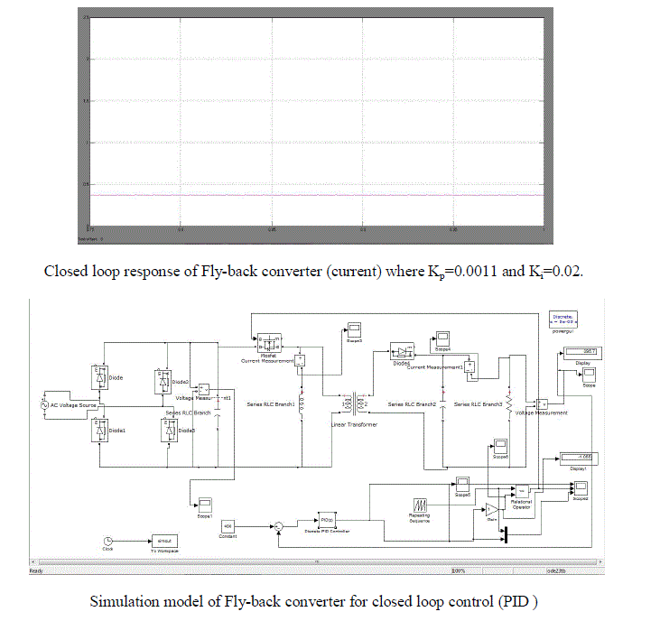 |
| The simulink Schematic of Fly-back converter with PI controller is shown in figure. The output voltage senses Vout and compared with the input Vref. An error signal is produce which is processed through PI controller to generate a control voltage. |
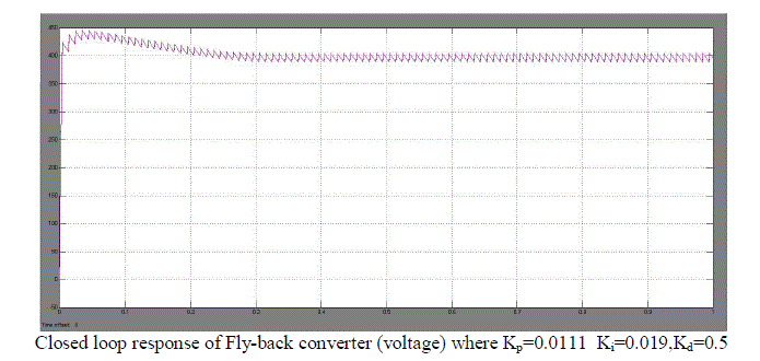 |
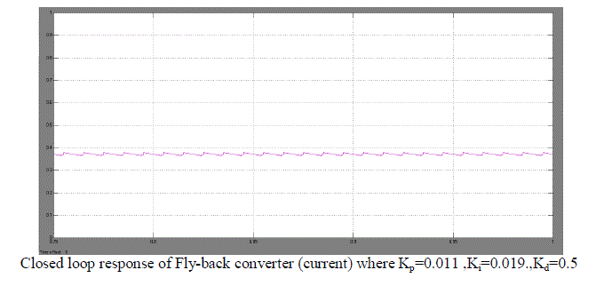
| Where the values of parameter are, Input voltage [Vin]=220 volts, Output voltage [Vout]=440volt, Switching frequency=25kHz, Inductor value=47.60mH, filter capacitor=600μF, current=0.375A. |
 |
| Therefore output values shows, there are variation in output voltage, and fluctuation is less, and output is shown in above fig. |
 |
| Table shows the various values of over shoot, settling time ,rise time for output voltage When Values of Kp and Ki where kept changing as shown, and the output current[I] was seen having constant value 0.375A. |
IV. CONCLUSION |
| Here a high step-up dc–dc converter using coupled inductor with proportional integral control is simulated. The designing of fly-back converters has been carried out for constant voltage applications considering inductor and capacitor as performance parameters. Fly-back converter has been designed to deliver 400 volts DC to a 150 watt load. Performance and applicability of this converter is presented on the basis of simulation in MATLAB SIMULINK. Flyback converters are employed for LOW POWER applications below 150 W and with voltages below 500V. Note that the core with an air gap doubles as a transformer and an output choke— saving one heavy and costly component. Now cut the electrical connection between the two parallel inductors and use only magnetic coupling between the two L’s by purposefully winding them on the same magnetic core. This makes for a two winding inductor--each separately wound and isolated electrically from each other except for the common magnetic core coupling . We now lose the common ground. Current no longer flows simultaneously in the two electrically isolated inductor windings due to the core coupling alone because the primary and the secondary have their own series switches. Moreover, these switches can act a complementary fashion so that when one is on the other is off. |
| By the capacitor charged in parallel and discharged in series by the coupled inductor, high step-up voltage gain of 400V is achieved. As the output voltage of the converter with PI Control has minimum overshoot and produces a constant output current shown. These studies could solve many types of problems regardless on stability because as we know that proportional integral controller is an intelligent controller to their appliances. |
| In open loop system, the fluctuation is more, when we added a controller that is close loop, the output was constant. |
References |
|