In this paper a high performance Ultra Wide Band microstrip bandpass filter is presented. The filter is designed using λ/4 short circuited stubs to improve the performance of UWB. The designed filter is based on 5th order chebyshev low pass prototype with .1 dB passband ripples. The filter with total size of 45×11 mm operates within 3.13-10.4 GHz, produces a fractional bandwidth of 106%. The filter is designed on a polystyrene substrate with relative dielectric constant of 2.6 and a thickness of 1.27mm. The simulated result using HFSS shows an insertion loss (S21) less than -0.1dB and return loss (S11) better than -16.5 dB. Group delay is also flat in passband.
Keywords |
| Microwave filter; UWB; microstrip; quarter wavelength; short circuited stubs. |
INTRODUCTION |
| THE demand in high speed communication has led to the design and development of wide band filters to support the
applications such as UWB technology that promises communication speed of up to 1000 Mbps. Because of its attractive
feature in high speed wireless applications, the ultra wide band communication has been authorized by federal
communication commission (FCC) with unlicensed frequency spectrum of 7.5GHz from 3.1 GHz to 10.6 GHz in February
14,2002 [1].The UWB used at a very low power level for short range, high bandwidth communication using a large part of
radio spectrum. The key passive component in UWB is front end receiver required to meet some stringent specifications
compactness, low insertion better return loss . Considering above said requirements researchers have proposed and
developed many UWB bandpass filters using different methodologies and structures [2-11]. However minimizing these
parameters with optimum size has always been a challenging task. |
| A broadband filter using interdigital bandpass filter microstrip line resonator was presented in [2] with a maximum
bandwidth up to66%.In [5] UWB filter is designed using transmission line stubs. Proposed filter achieved insertion loss
about-0.1dB, return loss better than -16.5dB and FBW of 106%. The filter proposed in [6] is designed using a slow wave
coplanar waveguide MMR. A passband of 3.1 to 10.6 GHz is achieved with .9dB insertion loss and a return loss better than
10 dB. In [7] a quintuple UWB bandpass filter is designed using a multiple stub loaded resonator shows an insertion loss
about 1.4 dB and a fractional bandwidth about 117%. In [8] a compact notched UWB filter with improved out of band
performance is proposed using the technique of quasi electromagnetic bandgap (EBG) structure achieved insertion loss
about 1.7 dB and return loss about 10 dB in the passband .A multimode resonator is proposed in [9] which is constructed by
cascading interdigital coupled microstrip line sections with short- ended stepped impedance stubs being loaded. The
realized filter achieved insertion loss about .7dB with a fractional bandwidth of 106%. .Most of the above discussed
technique provide insertion loss about 1 dB and return loss is better than 10 dB. Also the dimensions which are to be
implemented are very small which required high resolution lithography machines hence increasing the overall cost of filter.
In the present design five short circuited quarter wavelength stubs are utilized to achieve UWB filter characteristics. Optimization and parameterization of designed parameters (lengths and width) is done in order to achieve improved results.
The design procedure is discussed in next section. |
LITERATURE SURVEY |
| C. Nguyen [10] A new, compact, very-broadband bandpass filter, consisting of two-parallel-conductor short-circuited spur
line resonators, a quarter-wavelength long, is described. This filter Possess a very wide bandwidth, more than 5:l. A
microstrip filter having a passband from 1.8 to 9.2GHz has been designed and tested with less than 1dB insertion loss.
Filter is very attractive for wideband microwave integrated circuits due to its compactness and very wide bandwidth. |
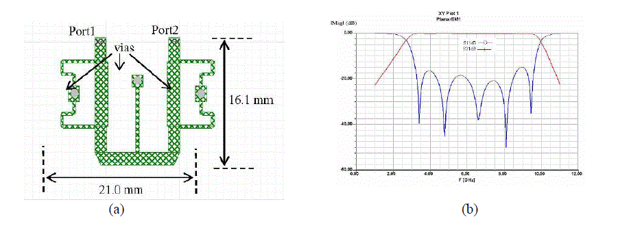
| Mohammad ShahrazelRazalli, Alyani Ismail [11] presents a compact 5 poles Ultra-
Wideband (UWB) microwave filter that uses a quarter wave short-circuited stubs. The microwave filter pattern layout as
shown in Fig 1.1(a). The overall size of the filter is reduced to 16.1mm x21.0mm as compare to the filter designed using
conventional short circuit stub technique 41mm x 12mm. |
| The UWB bandwidth is obtained from 2.72GHz to9.94GHz. The filter shows an insertion loss of than 0.8 dB, the
maximum peak of return loss (Sll) is at -14.88 dB at 9 GHz with the centre frequency of6.33 GHz. |
| Thai Hoa Duong and Ihn S. Kim [12] proposes a modified short-circuited stub bandpass filter suitable for ultra-wideband
applications utilizing low temperature co-fired ceramic (LTCC). By modifying the conventional short-circuited stub
bandpass filter structure with lower characteristic impedances for stubs and connecting lines ,the number of stubs has been
reduced from 5 to 2 stubs on a high dielectric constant substrate ( εr = 40). A wireless local area network (WLAN) stopband
in the frequency range of 5.15 to 5.825 GHz has been inserted into the filter characteristic using three short-circuited
coupled lines. An insertion loss less than 1.0dB and return loss better than 10 dB in the pass bands have been measured. A
FBW of 109.49% has been achieved. The dimension of the filter is 4 × 8 × 0.57 mm3. |
UWB FILTER DESIGN |
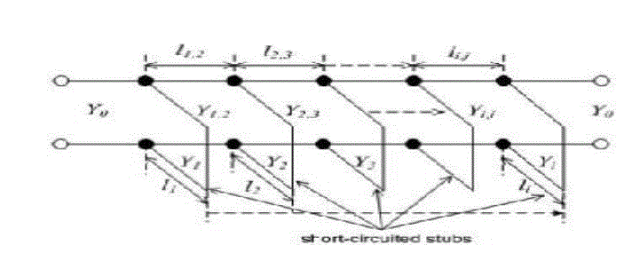
| The design is based on a low pass chebychev filter prototype with .1 dB passband ripples. The equivalent structure for short
circuited stub filter is shown in figure1[13]. |
| Here, UWB with centre frequency 6.85GHz and fraction bandwidth 1.06 is designed on a 1.27 mm substrate thick
polystyrene substrate with dielectric constant εr=2.6 and simulated using HFSS. |
 (1) (1) |
 (2) (2) |
 (3) (3) |
 (4) (4) |
 (5) (5) |
 (6) (6) |
 (7) (7) |
| The model in figure 1 is derived from J inverters by using conventional filter design and the line admittances, Yi,i+1 given
to fulfill the specifications. The separation distance between the stubs are denoted by li,j whereas stub length is given by
li. For designing the proposed filter first a 5th order chebychev low pass prototype with .1dB passband ripples is selected
[14]. Low pass filter prototype parameters are given as : g0=g6=1,g1=g5=1.1468, g2=g4=1.3712and g3=1.9750.With these
prototype values following design equations are solved for calculating admittances values for stubs and connecting lines.
Where |
 (8) (8) |
| The stub length and separation depend
on characteristics admittances, Yi, and transmission line admittances,Yi,i+1.
The transmission line admittances, Yi,i+1 can be obtained by using Eq.(9)[13]. |
 (9) (9) |
| The calculated admittances and impedances for five short- circuited stubs (Yi and Zi) and transmission lines (Yi,i+1 and
Zi,i+1) are applied to standard equations for microstrip [13] to obtain the dimension of line given by Table 1.The
characteristic admittance of input and output lines are taken as 50 Ω for better impedance matching. |
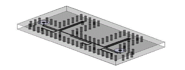
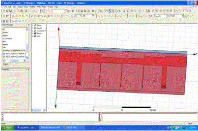
| Each stub in figure1.4 is short circuited to ground through a via at each end. The structure in figure 1.4 is simulated using
HFSSwith stub dimension shown in table 1. To get better results dimensions are adjusted slightly to get better results. |
RESULTS AND DISCUSSION |
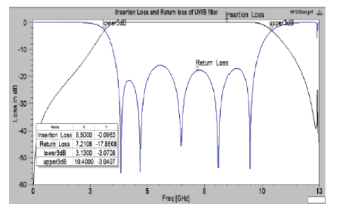
| Filter is designed using a low cost 1.27 mm thick polystyrene substrate of relative dielectric constant εr=2.6.The minimum
dimension of filter i.e 0.21mm which can be realized using simple optical lithography or micromachining technique. The
simulated results of scattering parameters using HFSS is shown below in figure 3. The size of as designed UWB filter
size (45mmx11mm ).The measured results show an in-band insertion loss of -0.1dB in the entire passband of 7.27 GHz thus
providing lowest insertion loss when compared with minimum insertion loss(<0.7dB) as shown in Table 2. The filter shows
return loss better than 16.5dB thus good impedance matching is achieved at the I/O ports. The designed filter gives a 3-dB
fractional bandwidth of 106% from 3.12 GHz to10.4 GHz |
| Hence almost entire band allocated by FCC is utilized. The phase response is ripple free in entire pass band of
7.27GHz.Thus the simulated scattering parameters that designed filter has a stable and excellent performance over entire
UWB spectrum |
| CONCLUSION |
| An UWB microwave filter utilizing quarter wavelength short-circuited stubs has been designed. Detailed parametric
analysis is done successfully to achieve a low loss and good performance UWB filter . The simulated scattering parameters
and phase response over the others discussed in Table 2 proved that filter has excellent characteristics i.e flat group delay,
low insertion loss and better return loss over entire UWB spectrum and can widely be used in wireless personal area
network (WPAN) applications, wireless monitors ,sensor networks, imaging system which include Ground Penetrating
Radar (GPR) system etc. |
Tables at a glance |
 |
 |
| Table 1 |
Table 2 |
|
Figures at a glance |
 |
 |
 |
 |
 |
| Figure 1 |
Figure 2 |
Figure 3 |
Figure 4 |
Figure 5 |
|
References |
- Transition.fcc.gov/Bureaus/Engineering_Technology/Orders/2002/fcc02048.
- G. Zhang, M. J. Lancaster, F. Huang, Y. Pan, and N. Roddis, “Wideband microstripbandpass filter for radio astronomy application,” in Proc. 36thEur. Microw. Conf., , pp. 661–663, Sep. 2006.
- Razalli, M. S., A. Ismail, M. A. Mahdi, and M. N. Hamidon, “Ultra- wide band microwave filter utilizing quarter-wavelength short- circuited stubs,” Microwave Optical Technology Letters, Vol. 50, No. 11,2981–2983, November 2008.
- P. Cai, Z. Ma, X. Guan, Y. Kobayashi, T. Anada and Gen Hagiwara,“A Novel compact ultra-wideband bandpass filter using a microstripsteppedimpedance four-modes resonator,” 2007 IEEE MTT-S International Microwave Symposium Digest, pp.751-754.
- Q.X. Chu , X.H. Wu, and X.K. Tian , “Novel UWB bandpass filter using stub loaded,” IEEE Microw. Wirlesscompon. Lett.,vol.21, no.8,pp.403-405, Aug.2011.
- V. Sekar and K. Entesari. “Miniaturised UWB bandpass filters with notch using slow-wave CPW multiple-mode resonators,” IEEE Microw. Wirlesscompon. Lett.,vol.21, no.2,pp.80-82, Aug.2011.
- X. H. Wu, Q.X. Chu, X..K. Tian ,and X. Ouyang, “Quintuple-mode UWB bandpass filter with sharp roll-off and super-wide upper stopband ,” IEEEMicrow.Wirlesscompon. Lett.,vol.21, no.12,pp.661-663, Dec. 2011
- Gao, M. J., L. S. Wu, and J. F. Mao, “ Compact Notched Ultra- Wideband Band Pass Filter With improved Out -of-Band Performance Using Quasi- Electromagnetic Band Gap Structure,” Progress In Electromagnetics Research, Vol. 125, 137-150, 2012
- Z. Zhang and F. X iao, “An UWB bandpass filter based On a novel type of multi-mode resonator,” IEEE Microw. Wirlesscompon. Lett.,vol.22, no.22,pp.506-508, oct.2012.
- C. Nguyen, “Development of New Miniaturized Bandpass Filter having Ultrawide Bandwidth”, Electronics Letters, Vol. 30, 12th May 1994.
- Mohammad ShahrazelRazalli and Alyani Ismail, “Compact Configuration Ultra- Wideband Microwave Filter using Quarter-Wave Length Short- Circuited Stub”, Proceedings of Asia-Pacific Microwave Conference, 2007.
- Thai Hoa Duong and Ihn S. Kim, “A Modified λ0/4 Short-Circuited Stub Bandpass Filter with WLAN Stopband for UWB Applications”, Proceedings of the 38th European Microwave Conference, October-2008.
- Jia Sheng Hong and M.J. Lancaster, Microstrip filters forRF/Microwave Applications, John Wiley & Sons, 2001
- Yue He and YuliangDongi, “A Novel Compact UWB Bandpass Filter with Quarter-Wave Short-Circuited Stubs”, International Symposium on Intelligent Signal Processing and Communication Systems (lSPACS 2010) December 6-8, 2010.
- Hussein Shaman, Student Member, IEEE, and Jia-Sheng Hong, Senior Member, “Ultra Wideband (UWB) Bandpass Filter with Embedded Band Notch Structures”, IEEE Microwave and Wireless Components Letters, Vol. 17, No. 3, March 2007.
- SaiWai Wong and Lei Zhu, “A Stopband-Enhanced UWB Bandpass Filter using Short-/Open- Stubs Embedded Ring Resonator”, IEEE, 2009.
- J.Q. Huang, Q.X. Chu and C.Y. Liu, “Compact UWB Filter Based on Surface-Coupled Structure with Dual Notched Bands”, Progress In Electromagnetic Research, Vol. 106, 311-319, 2010.
|