In this paper, an improved design of a tunable optical filter device made up of alternating layers of MgF2 and Ta2O5is proposed. Different configurations of this narrow band pass (NBP) optical filter are used for whole visible spectral range (400nm-700nm).We report on the calculated values of the design parameters, such as pass band wavelength, 3-dB bandwidth and quality factor for different configurations of narrow band pass optical filter. The design parameters are also evaluated when varying the angle at which the optical wave is incident on the input layer of the filter.
Keywords |
| tunable optical filters,pass band wavelength, 3-dB bandwidth, quality factor. |
INTRODUCTION |
| Multichannel optical communication system was made possible by the realization of several optical components. An
optical filter is one of the critical components used to increase the channel information capacity of the optical fiber. The
fiber optics communication systems uses various types of interference filters such as multilayer thin films,wavelength
selective filters, Fiber Bragg grating interference filters etc.[1] [2] [3] [4].The priority task for the developers is to
obtain maximal selectivity and maintainability of the filters using minimal number of thin−film layers in the structures.
These filters determine the overall efficiency of the system. Recently, there has been a growing interest in the
application of interference filters in the visible spectral range from 400nm to 700nm owing to their application in
display and sensor devices which in turn are used in the field of life science, imaging, industrial, or defense industries.
Multilayer interference structures of thin films with low andhigh refractive index materials and filters on the base
ofsuch structures are known for a long time. Design and realization of interference coatings are the principal stages in
production of thin−film systems with givencharacteristics [5] [6]. The system of reflected and refracted waves appears
at wave propagation processes in layer structure and forms multiple interference patterns. Modifying the structure of
layeredmedium in terms of physical properties of layer materials, thickness of the layers and number of layers allows
for controlling thecharacteristics of wave processes to a large extent. Interference filters can include some tens or even
hundreds of dielectric layers.[7][8].In this paper, we present different configurations of multilayer interference filter
made up of alternating layers of MgF2 and Ta2O5 and calculate the design parameters such as pass band wavelength, 3-
dB bandwidth and quality factor by using Transfer matrix Method forthe visible spectral range from 400nm to 700nm. |
II. STRUCTURE AND PRINCIPLEs |
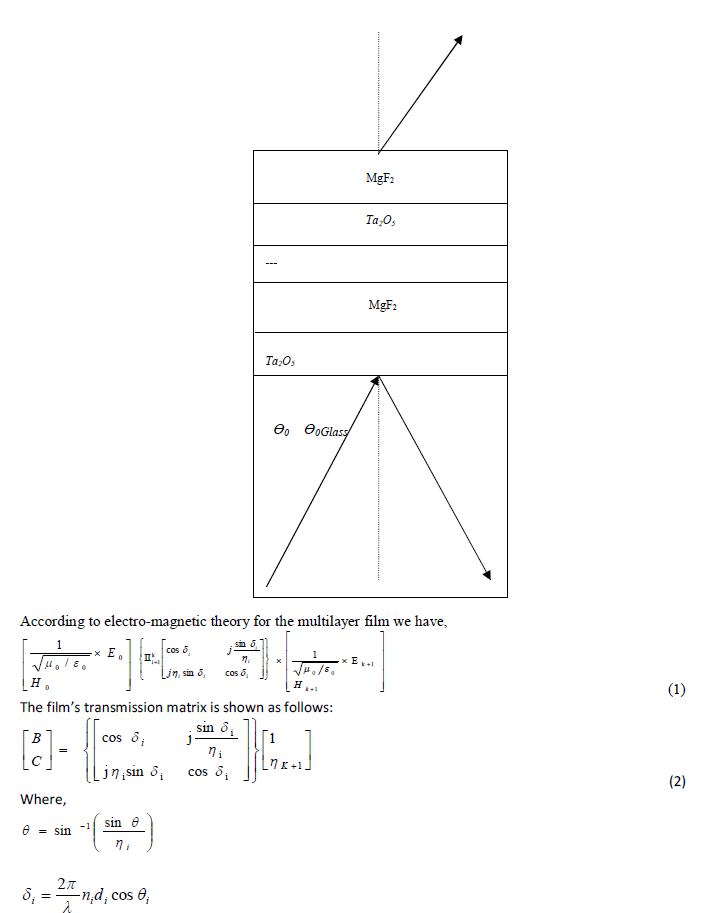
| Generally,an interference narrow band pass(NBP)optical filterconsists of alternating layers of H and L, film, alternating
layers of H and L,…, film, alternating layers of H and L. Here, H and L indicate high and low index layers
respectively, with a common thickness of quarter wavelength. Also, the film consists of 2n’H’ or 2n’L’ where n is an
integer and determines the length of the cavity. It consists of alternating MgF2 andTa2O5layers deposited over glass
substrate. |
 |
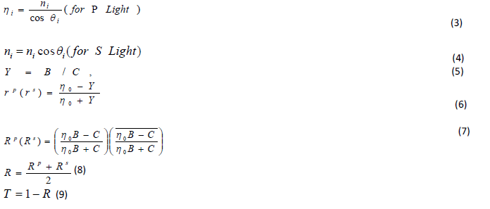 |
| Thus transmission is calculated by using equation (9). |
III. DESIGN PARAMETERS OF DIFFERENT CONFIGURATION |
| The transmittance of layered structure is calculated according to thin film equations using MATLAB 2012 software.
We have concentrated mainly on obtaining the precise design parameters rather than the computation time required.
The design parameters which control the transmission characteristics are the value of pass wavelength, 3-dB bandwidth
or Full Width at Half Maximum (FWHM) and quality factor. The 3-dB bandwidth or Full Width at Half Maximum
(FWHM,) in the case of the pattern in transmitted light, is the width between the points on either side of a maximum
where the intensity has fallen to half its maximum value. It is a measure of the sharpness of the fringes. Another
parameter that determines the performance of the device is the quality factor of the filter, which is given by the ratio of
the pass band wavelength to the 3-dB bandwidth. The quality factor is a measure of selectivity.
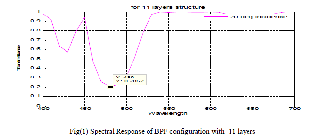
Figure 1 shows spectral Response of NBP filter configuration with 11 layers and 1 cavity according to cavity
length(n) for a filter configuration ‘substrate/ LHLHL(2nH)LHLHL/ cover’ and a pass wavelength of 480 nm. |
 |
| Figure 2 shows spectral Response of NBP filter configuration with 19 layers and 1 cavity according to cavity
length(n) for a filter configuration ‘substrate/ LHLHLHLHL (2nH) LHLHLHLHL / cover’ and a pass wavelength of
480 nm. |
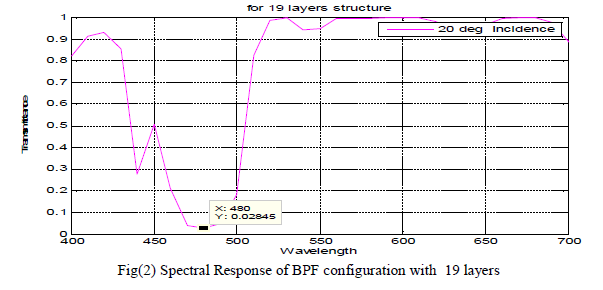 |
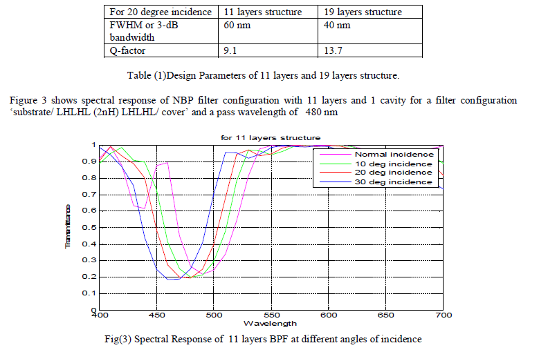
| The numerical values of the design parameters,i.e. 3-dB bandwidth and quality factor, are obtained from figure (1) and
figure (2)are given in Table (1).It is observed that, as the number of layers increase, the cut-off characteristic sharpness
increases and there is a sharp decrease in the value of 3-dB bandwidth. This makes the filter efficient with a better
quality factor. |
 |
| Figure 4 shows spectral Response of NBP filter configuration with 19 layers and 1 cavity for a filter configuration
‘substrate/ LHLHLHLHL (2nH) LHLHLHLHL / cover’ and a pass wavelength of 480nm. |
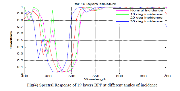 |
| It is observed that in case of both the structures, as angle of incidence increases, pass wavelength shifts to lower values,
which indicates that this type of configuration can be used as tunable filter for wavelength 400-700 nm. Table 2 gives
the corresponding values of the wavelength of minimum loss due to reflection.
It is observed from figures (3) and (4) that, at a tilt of 20 degree incidence, the minimum loss due to reflection occurs
at the pass wavelength for which the filter is designed i.e. 480 nm. As the angle of incidence decrease, the passband
shifts to higher wavelengths such as 485nm at a tilt of 10 degree and 490 nm at normal incidence. As the angle of
incidence increases, the passband shifts to shorter wavelengths such as 470 nm at a tilt of 30 degree. Thus, the filter can
be made tunable. |
 |
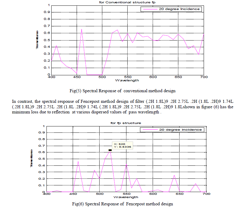
| Figure (5) shows the spectral response of filter configuration under conventional design method [8] with a
configuration of (1H 1L 1H 1L 1H 1L )3 2H (1L 1H 1L 1H 1L 1H)3 1L (1H 1L 1H 1L 1H 1L)3 2H (1L 1H 1L 1H 1L
1H)3 1L (1H 1L 1H 1L 1H 1L)3 2H (1L 1H 1L 1H 1L 1H)3 .26569H 1.30674L.It is observed that the pass band is
comparatively larger ranging from minimum wavelength of 470 nm to maximum wavelength of 500 nm. This filter
behaves as a broadband filter.a |
 |
IV. CONCLUSION |
| Mathematical expressions have been given for the improved design of a tunable optical filter device made up of
alternating layers of MgF2 and Ta2O5 for whole visible spectral range (400nm-700nm).The optical interference effect
on the transmission characteristics of the filter is demonstrated in terms of parameters such as FWHM or 3-dB
bandwidth and Quality factor are calculated. We have carried out a comparative study of the spectral response of the
optical filter for different number of layers, conventional design and fencepost design. Also, a variation in the
wavelength of minimum loss due to reflection is observed for different angle of incidence. Increasing angle of
incidence from normal to 30 degree shows shift of wavelength at lower values. Thus, by varying the angle of incidence,
the filter can be made tunable.Extensive research and development efforts are underway to realize such tunable filters
in the visible region experimentally, since such a device may serve as one of the basic building blocks in display and
sensor devices which in turn are used in the field of life science, imaging, industrial, or defense industries. Furthermore,
graded index structure of the materials can be analyzed to obtain enhanced filter characteristics. |
References |
- Macleod, Thin Film Optical Filters, third ed., 2001.
- Qiong-Hua Wang, Lei Li, ZhibingGe, Broadband dielectric film transflactor for variable transmission optical filters,Optik 122 (2011) 364âÃâ¬Ãâ366.
- B.J. Chun, C.K. Hwangbo, and J.S. Kim, Optical monitoring of non-quarter wave layers of dielectric multilayer filters using optical admittance,Opt. Express 14, (2006) 2473âÃâ¬Ãâ2479.
- M.R. Mokhtara,E.S.A.Rahmana, M.Ibsenb, H.A.AbdulRashida, H.Y.Wonga, M.Z.R.M. Zulkiflya, N.A.M.Arif ,Apodized fiber bragg grating with modulated refractive index change for transmissive gain euualisation, Optic (2010) G Model IJLEO-51348; No. of Pages3.
- S. Eliahou-Niv*, R. Dahan, G.Golan, Design and analysis of a novel tunable optical filter, Microelectronics Journal 37 (2006) 302âÃâ¬Ãâ307.
- A.V. Tikhonravov and M.K. Trubetskov, Mathematical modeling of multilayer filters for telecommunication, Comp. Math.Model.14, 74âÃâ¬Ãâ84 (2003).
- ShaliniGarg, R K Sinha and K L Deori, Design parameters of a tunable semiconductor multiple quantum well electron wav filter, Semiconductor Science and Technology(2003) 292-296.
- R.R.Willey, Design of Optical Thin Films using the âÃâ¬ÃÅFencepostâÃâ¬Ã Method,50th Annual Technical Conference Proceedings(2007),365-368.
|