ISSN ONLINE(2319-8753)PRINT(2347-6710)
ISSN ONLINE(2319-8753)PRINT(2347-6710)
| J.Surendar, Dr.N.Loganathan Department of Electrical and Electronics Engineering, K.S.Rangasamy College of Technology, Tiruchengode, Tamilnadu, India |
| Related article at Pubmed, Scholar Google |
Visit for more related articles at International Journal of Innovative Research in Science, Engineering and Technology
Transient current in power system is very common factor, due to many switching operations. This paper focusing on recovery capacitor switching transient has been proposed for system protection. It will protect from mal-operation of relay to improve the reliability of the system. During Group of generator switching, transformer switching, Series capacitor switching, Shunt capacitor switching, Tap-changing operations will cause high inrush current in radial distribution system. This work comprises of a radial feeder three phase system protection improvement deals with overcurrent relay. This approach significantly improves the performance of radial feeder protection under transient condition for the period of starting. The high inrush currents can do mal function of protective relays and it will cause a severe damage to the system and end user equipment. The series reactor load adopted to compensate current and voltage waveform problems of sensitive relays doing mal operation under transient conditions. The series reactor consists of a series inductor having a common for three phase load side. The extensive simulation results have been carried out in MATLAB/Simulink environment power system blockset toolboxes.
Keywords |
| Radial feeder protection, Capacitor switching, Series reactor, Transient current. |
INTRODUCTION |
| The function of protective relaying is to cause the quick removal from service of any element of a power system when it suffers a short circuit, or when it starts to operate in any abnormal manner that might cause damage or otherwise hold up with the effective operation of the rest of the system. A secondary function of protective relaying is to provide indication of the type of failure. Human observation and automatic oscillograph records are provided for analyzing the effectiveness of the faultprevention and features including the protective relaying itself. This paper will focus on the mal function of protective relay. Power system network consists of generators, transformers, circuit breakers, relay and transmission line and distribution circuits. Fault occurs on any part of the system, it must be quickly detect and disconnect from the system. There are two principle reasons for it. |
| Firstly, if the fault is not cleared quickly, it may cause unnecessary interruption of service to the customers. Secondly, rapid disconnection of faulted apparatus limits the amount of damage to it and prevents the effects of fault from spreading in to the other part of the system. This paper will focus on the mal function of protective relay. Back-up relaying is employed only for protection against short circuits. It causes short circuits are the major type of power failure, there are more opportunities for failure in short primary relaying. Consequently fail-to-trip may not lead to loss of more components, based on the fault is finally cleared by remote back up protection or just by local back up protection. But a mal operation of protective relay will always lead to loss of at least one component in the system. |
| In the presence of harmonic-producing loads, capacitors used for power factor correction can cause parallel or series resonance problems which tend to increase the total harmonic distortion (THD) of the voltage and current waveforms. This work considers the addition of a power factor correction capacitor, in the presence of harmonic loads and at the harmonic load site. In both the resonance created by the addition of the capacitor caused the harmonic distortion of the voltage and current waveforms to increase. Another problem is transient over voltages created by switching capacitor. Radial distribution has much potential to improve radial distribution system performance and it should be encouraged. |
| However, radial system designs and operating practices are normally based on radial power flows and this creates a special challenge to the successful introduction of insure that distribution generation will not degrade distribution system power quality, safety or reliability. The relay operating principle, design and application are presented as well as results from computer simulation studies and laboratory tests. A spectral analysis of voltage and current waves is made to extract the acceptable capacitor switching times by observing the transient over-voltages and current. The solution to mal-trips is dependents on many factor, but mainly the immunity of protective relays against the impact of any non-fault transient. |
CONFIGURATION OF RADIAL FEEDER PROTECTION |
| Transmission line protection presents many fundamental relaying considerations that apply to the protection of other types of system protection. Each electrical element will have problems unique to itself, but the concepts of reliability, selectivity, local and remote backup, zones of protection, coordination and speed which may be present in the protection of one or more other electrical apparatus are all present in the considerations surrounding transmission line protection. Transmission lines are also the links to adjacent lines or connected equipment; transmission line protection must be compatible with the protection of all of these other elements. This requires coordination of settings, operating times and characteristics. |
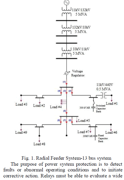 |
| variety of parameters to establish that corrective action is required. Obviously, a relay cannot prevent the fault. Its primary purpose is to detect the fault and take the necessary action to minimize the damage to the equipment or to the system. The most common parameters which reflect the presence of a fault are the voltages and currents at the terminals of the protected apparatus or at the appropriate zone boundaries. The fundamental problem in power system protection is to define the quantities that can differentiate between normal and abnormal conditions. This problem is compounded by the fact that ‘‘normal’’ in the present sense means outside the zone of protection. |
| Electric power distribution is the portion of the power delivery infra structure that takes the electricity from the highly meshed, high-voltage transmission circuits and delivers it to customers. Primary distribution lines are “medium-voltage” circuits, normally thought of as 600 V to 33 kV. At a distribution substation, a substation transformer takes the incoming transmission level voltage (132 to 33 kV) and steps it down to several distribution primary circuits, which fan out from the substation. Close to each end user, a distribution transformer takes the primary-distribution voltage and steps it down to a lowvoltage secondary circuit (commonly 33 kV/11 V other utilization voltages are used as well). From the distribution transformer, the secondary distribution circuits connect to the end user where the connection is made at the service entrance. |
| A. Structure of power system |
| Overview of the power generation and delivery infra structure and where distribution fits in. Functionally, distribution circuits are those that feed customers. Some also think of distribution as anything that is radial or anything that is below 33 kV. The distribution infra structure is extensive after all, electricity has to be delivered to customers concentrated in cities, customers in the suburbs, and customers in very remote regions few places in the industrialized world do not have electricity from a distribution system readily available. Distribution circuits are found along most secondary roads and streets. Construction is mainly overhead. A mainly utility may have less than 50 ft of distribution circuit for each customer. A rural utility can have over 300 ft of primary circuit per customer. |
| Extensive infra structure, distribution systems are capital intensive businesses. An Electric Power Research Institute (EPRI) survey found that the distribution plant asset carrying cost averages 49.5% of the total distribution resource (EPRI TR-109178, 1998). The next largest component is labour at 21.8%, followed by materials at 12.9%. Utility annual distribution budgets average about 10% of the capital investment in the distribution system. The growth of underground distribution system has been extremely rapid and as much as 70% of new residential construction is via underground systems. |
CONTROL OF CAPACITOR SWITCHING TRANSIENT |
| The capacitor-switching transients can be controlled by many methods in nature. It can prevent the protective relay and end user equipment from non-fault condition. |
| 1. Series inrush-current-limiting reactors |
| 2. Resistance switching |
| 3. Point-of-wave switching (synchronous breakers) |
| 4. Application of surge arresters |
| 5. Dividing the capacitor bank into smaller size banks (the smaller the size of the capacitor bank being switched, the lesser is the transient) |
| 6. Avoiding the application of capacitors at multivoltage levels to eliminate the possibilities of secondary resonance |
| 7. Coordination with utility, if the utility capacitors are located close to the distribution system |
| 8. Considering steady-state voltage rise due to application of capacitors. The transformer taps may have to be adjusted. |
CAPACITOR SPECIFICATIONS |
| The specifications for capacitors are identified by the industry standards. They include tolerances and acceptable operating ranges. The capacitors shell be capable of continuous operating without exceeding the following limits. |
| i. 110% of peak voltage |
| ii. 120% of rms voltage |
| iii. 135% of name plate Kvar |
| iv. 180% of nominal rms current based on rated kVAR and rated voltage. |
| A. Voltage |
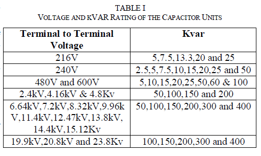
| Nominal system voltages are specified line to line. The capacitor units are single phase and appropriate phase voltage is to be used. Capacitors are capable of operation at 110% of rated rms voltage and the crest should not exceed 1.2√2 rated rms voltage. The max operating voltages for shunt capacitors are listed in table I. |
 |
| B. kVAR Rating |
| Capacitor unit ratings are specified in kVAR. Normally available capacitor ratings are 50, 100, 150, 200, 300 and 400kVAR per unit. The capacitor units are capable of continuous operation but exceeding 135% of name plate kVAR. The typical kVAR ratings are listed in table. If the operating voltage increases or decreases from the nominal operating voltage, then the kVAR delivered changes accordingly. |
| kVAR delivered = Rated kVAR(Operating Voltage/Rated Voltage)2 |
| C. Frequency |
| Power factor Capacitors are designed for operation at 50 or 60Hz. The capacitor kVAR output is directly proportional to the system operating frequency. If the capacitor operates at a different frequency then the rated frequency, then the kVAR delivered is: |
| kVAR delivered = Rated kVAR(Operating Frequency/Rated Frequency) |
| By adding series current-limiting reactors can be reduced amplitude of the inrush current. But hardware implementation is very high cost. The dynamic modification of pickup current as a function of the load current. It increases the sensitivity in the most probable operating state. But it takes time and manual operation. The algorithm can be used online, since immediately after the switching instant, it can be applied. During transient cannot do any prediction. Capacitor switching is one of the common causes of an overvoltage transient encountered in power systems. Transient can be measured in this method. The phenomena adversely affect the voltage in radial system, resulting in the nuisance tripping at the customer terminals or even damage to sensitive equipments (Electromagnetic Transients Program). Although the proposed method is tested on a distribution system, its application is not limited only to radial power systems and can be used in all distribution systems. The drawback of using this method in over-current protections is the need to measure voltage in addition to current that increases the cost of hardware implementation. |
SIMULATION |
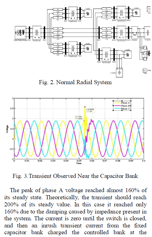
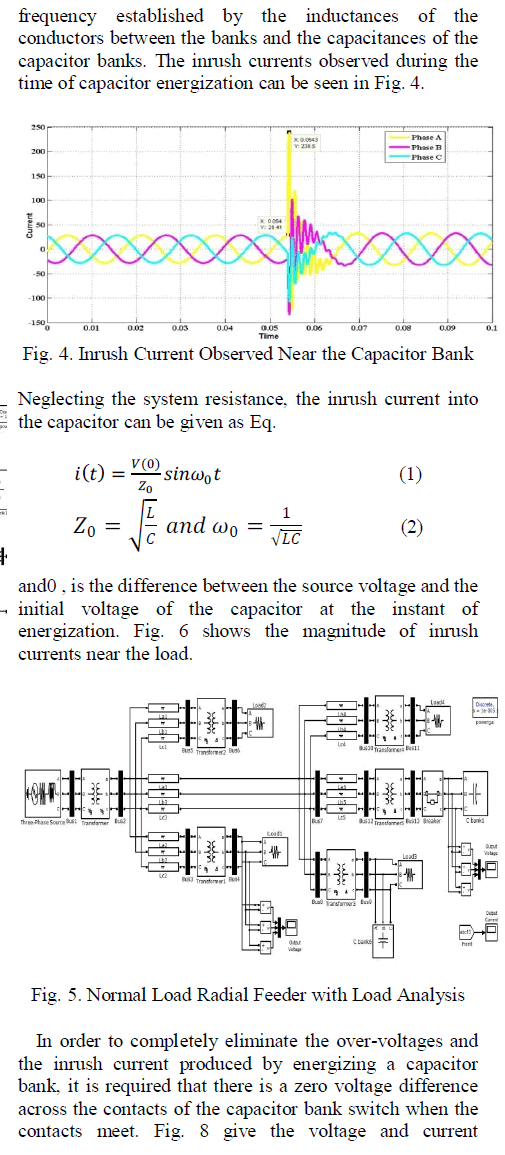
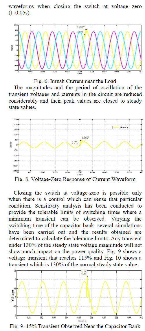
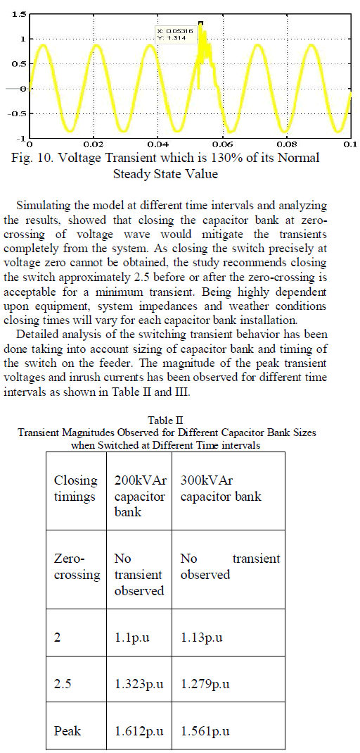
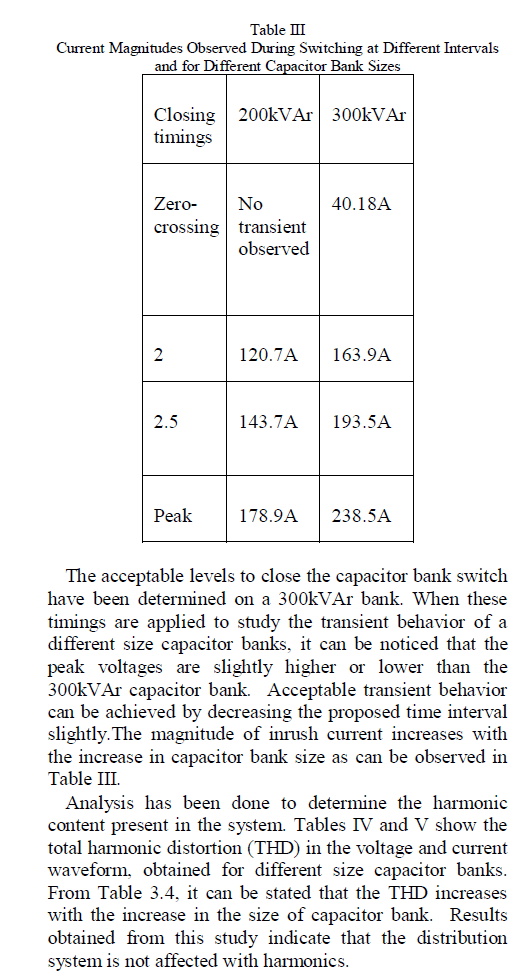
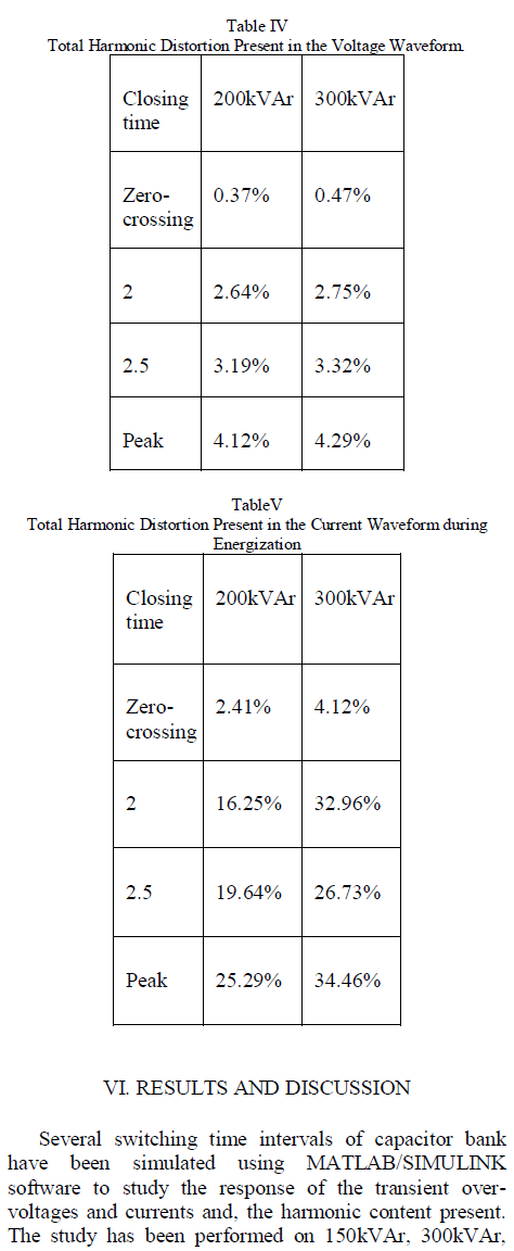
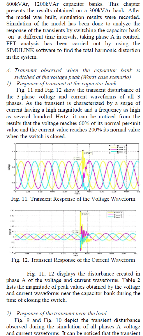
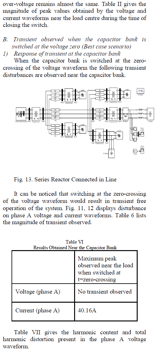
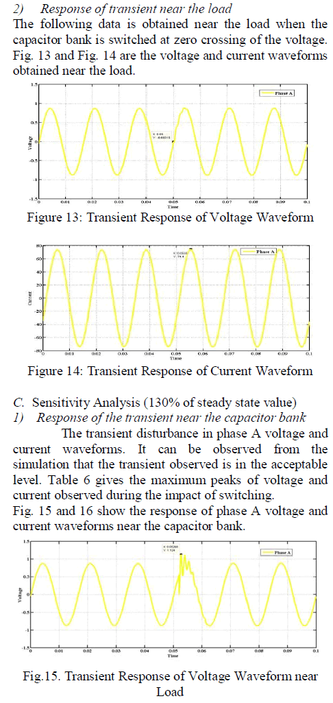
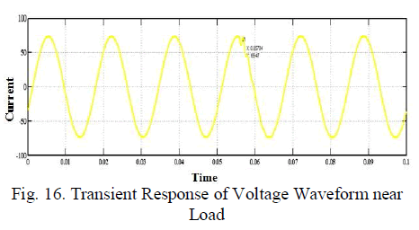
| The controlled capacitor bank is switched into the feeder to evaluate its effect on the feeder. The peak transient voltages, harmonics, and the high frequency inrush currents that originated as a result of this switching operation near the capacitor bank and near the load are concentrated. The controlled capacitor bank switch was closed at 5.4ms where the voltage of phase A reaches its peak value. Fig. 2. shows the transient response of the three-phase voltages near the capacitor bank before and after the switching operation. |
 |
 |
 |
 |
 |
 |
 |
 |
 |
 |
| Under transient condition made by testing them with the same group of relays. The one whose final tested waveform is above the others has better mal-trip immunity. During the development of a relay, the longest practical line length may be taken. For the setting of a specific relay, the actual line length can be taken. The waveform have to be determined for different operational states and for switching instants. |
CONCLUSIONS |
| The fault discrimination has achieved in the overcurrent relays at the time of capacitor bank starting. In existing system capacitor bank were used to compensate the power factor improvement. The new technique is implemented using to improve the immunity against switching transients due to switching capacitor bank in the IEEE 13-bus radial distribution systems. The simulation result of the proposed method is improved the reliable operation of radial system. High sensitivity sometimes causes undesirable operation of the relays and it considered reduced by this proposed method. Causal Productions has used its best efforts to ensure that the templates have the same appearance. |
ACKNOWLEDGMENT |
| This work funded by Energimyndigheten, Elforsk and ABB Automation products, Sweden. The authors would like to think F. Wang and M.H.J. Bollen Electric Power Systems Research and Energy Research. |
References |
|