ISSN ONLINE(2278-8875) PRINT (2320-3765)
ISSN ONLINE(2278-8875) PRINT (2320-3765)
Gaurav .R. Thakur1, Ankita .A. Chauhan1, Rajat .M. Agrawal2
|
| Related article at Pubmed, Scholar Google |
Visit for more related articles at International Journal of Advanced Research in Electrical, Electronics and Instrumentation Engineering
Dexterous robot arms are capable of manoeuvring in highly-confined spaces due to their high flexibility. With the potential in many applications, the optimum design of these robots in terms of configurations and control has attracted much interest and research. This paper deals with a cooperative robotics support of dexterous robot arms, which is supposed to be utilized for space exposed experiments on the Multi Access Test and Observation Facility (MATOF). The MATOF is proposed to provide a user-friendly experimental facility for various users of space utilization. ROS (Robot Operating System) has been emerging as a standard for robot software development. It is an open-source, meta-operating system that provides hardware abstraction services. It implements low and high level functionality components addressing robot perception, control and planning, focusing on the modularity and reusability of code contributed by a growing user community.ROS is designed to be as thin as possible, with no wrapping of user code so that it can be used with other robot software frameworks. The preferred development model is to have ROS independent libraries with clean interfaces. It is language independent, easy to use and scalable to large runtime systems and processes.
Keywords |
| Robot, Actuator, Controllers, Potentiometer, Sensors, Robonauts, Transmission. |
INTRODUCTION |
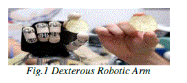
| Robots have always had a fascination in our mind. With their various applications in various fields, they have become a common part in our daily life. They are meant to ease our work and increase our comfort of living. The term ‘robot’ got prominence way back in the 1950s when Karl Capek in his play Rossum’s Universal Robots denoted the birth of a superior race that had intelligence similar to that of humans. A robotic arm is a robot manipulator, usually programmable, with similar functions to a human arm. It can be used to reduce the human effort required in heavy industries. It can also be used in situations where human intervention can lead to fatal results or is not possible as shown in fig.1 |
 |
| The most accepted definition of a Robot provided by the Robotics Institute of America in 1979 is that: |
| “A robot is a reprogrammable multifunctional manipulator designed to move material, Parts, tools or specialized devices through variable programmed motions for the Performance of a variety of tasks”. Robotics is that branch which involves with the study and applications of Robots. The goal of Robotics is to mimic natural world as closely as possible. Robotics is a relatively new field of engineering (about approximately 50 years old) and is finding many applications in different areas. With growing developments in the field of mechatronics and mathematic modeling, Robotics has come a long way. From an iron piece that could move only a few inches, there are now machines capable of jumping from high rise buildings, detecting landmines, performing complicated operations, and troubleshooting. |
| Force Based Search |
| When designing an assembly, force feedback and control abilities are critical. Assembly processes can be divided into four common steps: part location, shape insertion, gear meshing and snap fitting. Sometimes, the assembly features (such as holes or surfaces) are not visible so the use of vision is useless. In these situations, force based search strategies are required. In order to pinpoint the assembly feature you wish to work on, force feedback and control can be very useful. A common procedure is to normalize the torque on the Tool Center Point (TCP). Then, align the TCP on the assembly point and normalize the force applied. Often you might want to move the tool maintaining this force while monitoring the force feedback. When the assembly feature you are looking for has been found, a change in the force will be recorded, for example, when the part has snapped into place. This technique is very useful for many operations such as surface finishing (grinding, polishing...) or quality assurance inspection where force control and monitoring is important. |
| Force Control |
| There are two important step to consider in controlling applied force. The first step is to sense the force induced. This is often done through a force/torque transducer attached to the tool flange or joint torque sensor. Another way to do this is to monitor these forces; and less used these days, is to monitor the motor current and infer the joint torque from these values. The second step is about controlling the input force. This is achieved by input sensor readings, output joint torques or through a closed feedback loop. |
| Regardless of the method used, faster reactions are preferable. This can be done by, increasing the control update rate, changing control parameters or reducing the inertia of the robot. |
| Collaborative Robots |
| The methods and technologies that were discussed at the conference are mainly responsible for the new collaborative features of todays robots. They allow the robots to feel their environment and react to it. We can easily say that KUKA LightWeight robots are a good example. Each joint has its own force sensor to monitor external forces and force control. Having experienced it, the Robotiq team was really impressed by the fluidity of its movements when moved by hand. Rethink Robotics is also using this technology with Baxter. This dual arm robot also has integrated force sensors at each joint. To accomplish force control, Rethink Robotics used elastic actuators. Moreover, Baxter has integrated cameras in each arm for vision guided movement and visual object identification. |
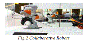 |
| All these new components are necessary to allow human-robot collaboration in a safe environment.[1]. |
 |
| The present scenario of Robotics is unimaginable from just some stipulated motions to performing various complex operations and space visits, Robots have found their application in all fields. The role of robot end-of-arm tooling has never been more important. With robot users demanding more versatility in their processes, manufacturers are under pressure to deliver flexible, intelligent end-of-arm tooling (EOAT) that adds value to the overall system. From servo grippers and hybrid tooling, to advanced tool changers and control modules, today’s EOAT is not only easier to implement and easier to use, it’s down right smart. Application-specific grippers are bringing robotics within arm’s length of a broader audience, to new industries and small to midsized businesses that would have considered it out of reach just a year ago. A new breed of anthropomorphic end effector not only plays nice in the lab, it’s finding its way onto the shop floor. And a magnetic gripper that’s the polar opposite of anything on the market is attracting fans. Pick and place, weld, deburr, apply material, inspect and locate, load/unload – and do it all with one EOAT – robot users are throwing down the gauntlet, and manufacturers are raising their “hands” to the challenge.[2] |
CLASSIFICATION OF ROBOTS |
| Robots are classified depending upon the circuitry of the Robots and the ranges of application. The classifications of Robots are into three types: |
| • Simple level Robots |
| • Middle level Robots |
| • Complex level Robots |
| Simple Level Robots |
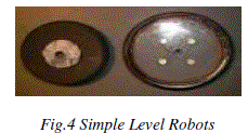 |
| They are automatic machines that extend human potential. They cannot be programmed and does not contain a complex circuitry |
| .E.g.: The best example of a simple level Robot is a semi automatic washing machine. |
| III. II Middle Level Robots |
| They are those Robots which can be programmed but cannot be reprogrammed. They are multi purpose devices. They have sensor based circuitry and can do work which humans do. E.g.: The best example of a middle level Robot is the fully automatic washing machine. |
| III.III Complex Level Robots |
| They are those Robots which can be programmed and also reprogrammed. They are reprogrammable, multifunctional, manipulators. They contain a model based circuitry and are very complex. |
| E.g.: The best example of a complex level Robot is the personal computer.[3] |
BLOCK DIAGRAM |
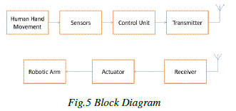 |
| • The sensors are mounted on our hand. These sensors detect any small movement that is made. |
| • On detecting the movement, the sensor, which is a potentiometer in our case, gives out a control signal. This control signal is in the form of analog voltage. |
| • This analog voltage is given as input to the microcontroller. |
| • The microcontroller converts this analog value into digital value using the analog to digital converter . |
| • This digital value is processed and depending on the processed value the actuators are activated. |
| • Depending on the value sensed by the sensor and the processed voltage value the motors are activated for different time intervals.[4] |
| • These time intervals are decided on the basis of different delay programs. |
| • Transmission of signals can be wired or wireless. |
The Mechanical Assembly |
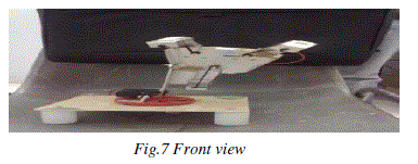
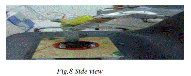
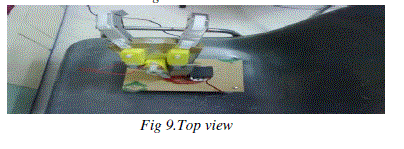
| The Robotic Arm consists of three fingers. Each finger has three rotary joints. Motion to the fingers is provided by means of cables. The cables are attached to the shaft of the motor. When the shaft rotates the cable is wound on the shaft of the motor causing the finger to bend. [7] |
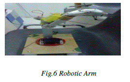 |
| The wrist joint is also a rotary joint to which the palm consisting of the fingers is attached. There is a servo motor at the wrist joint . |
PICTORIAL DESCRIPTION |
 |
 |
 |
Actuators |
| An Actuator is a device that makes the movement possible. The basic form of actuator is an electric motor. An actuator is a mechanical device that converts energy into motion. They are the devices that transform the input signal (mainly electrical) into electrical. The various electric motors used are: |
| 1. DC Motors: They are used to control the movement of fingers of robots. |
| 2. Servo Motors: They are used to control the wrist and elbow movements of the robots. |
| The actuators are typically linear or rotary actuators. Also they may be electric, pneumatic or hydraulic. Typically, electric actuators or motors are better suited to high speed, low load applications while hydraulic actuators do better at low speed and high load applications. Pneumatic actuators are like hydraulic actuators except that they are generally not used for high payload. The actuators are applied at the robotic arm end. These are used to facilitate the movements of the robotic arm. |
| Transmissions are elements between the actuators and the joints of the mechanical linkage. |
| • They are generally used for three reasons: |
| • Often the actuator output is not directly suitable for driving the robot linkage. |
| • The output of the actuator may be kinematically different from the joint motion. For example, the linear actuator is kinematically different from the elbow joint it drives. Thus the linkage consisting of the three passive joints and the linear actuator may be viewed as a transmission that converts the linear motion of the actuator to the rotary motion of the elbow joint. |
| • The actuators are usually big and heavy and often it is not practical to locate the actuator at the joint. First, big actuators have large inertias and they are harder to move around in space than the links that comprise the mechanical linkage. So it is desirable to locate them at a fixed base. Second, because of their size, they can impede the motion of one or more links of the robot. Thus, it is not uncommon to find linkages or cables that transmit the power from the actuator over a large distance to the joint. |
| Sensors |
| A sensor is a device that measures a physical quantity and converts it into a signal which can be read by an instrument. The control of a robotic arm is based on the correct interpretation of sensory information. This information can be obtained either internally to the robot (for example, joint positions and motor torque) or externally using a wide range of sensors. |
| Potentiometer |
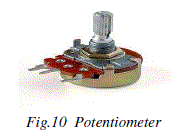 |
| The sensor used in our case is a potentiometer. A potentiometer (colloquially known as a "pot") is a three-terminal resistor with a sliding contact that forms an adjustable voltage divider. The sensors mounted on human fingers sense even the slightest movement made by them and accordingly send signals to the microcontroller. These signals are a result of change in the resistance value that invariably results due to the movement of our fingers. Due to the change in resistance continuously varying voltage signals are fed to the microcontroller. |
| The different types of sensors used are: |
| 1. Tactile Sensors |
| 2. Time flight sensors |
| 3. Compasses |
| 4. Miscellaneous |
| Controllers |
| The controller provides the intelligence that is necessary to control the Robotic Arm system. It looks at the sensory information and computes the control commands that must be sent to the actuators to carry out the specified task. |
 |
| The Controller Generally Includes: |
| • Memory to store the control program and the state of the robot system obtained from the sensors |
| • A computational unit (CPU) that computes the control commands |
| • The appropriate hardware to interface with the external world (sensors and actuators) |
| • The hardware for a user interface. |
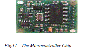
| We are using Atmel ATmega 32 microcontroller. It is an 8-bit microcontroller having an inbuilt analog to digital convertor(ADC). The ADC has 8 channels i.e it can convert 8 analog values to digital values. The resolution of ADC is of 10 bits.[8] |
| Microcontroller processes the analog signal and depending upon the given set of instructions it gives the desired output. This output acts as an input to the motor which leads to the movement of the robotic arm. |
APPLICATIONS |
| The robotic arm can be very useful in various fields. Its main job is to reduce human efforts. In works involving high machinery, hazardous situations and places which impose high difficulties for the working of human arm, the robotic arm can be a very effective tool. It provides flexibility in work and eliminates the problems of monotonous nature of job. The robot arms can be autonomous or controlled manually and can be used to perform a variety of tasks with great accuracy. It thus holds great importance in the following fields: |
| • The robotic arm can be fixed or mobile (i.e. wheeled) and can be designed for industrial or home applications. |
| • The robotic arm can also find great applications in the field of medicine. |
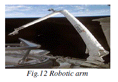
| • The robotic arm forms an integral part of the space shuttle system. E.g.-Shuttle Remote Manipulator System. |
 |
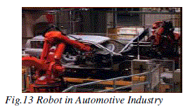
| Automotive industry is one of the most important partners in the development of robotic technologies. In automotive industry the Robotic arm are used for: |
| • Welding of various parts |
| • Robustness and precision of the assembly of pieces |
| • Manipulate very heavy loads |
| • Found in painting rooms for spray painting. |
| • Used for places that is hard to reach. |
 |
| Medical |
| • The robotic arm can be used in prosthesis. |
| Nuclear energy |
| • Nuclear generator installations are places where we can find a large number of robotic applications. |
| • Used for maintenance of nuclear reactors. |
| • Used for the replacement of radioactive fuel tubes. |
| • Seal off radioactive leakages in contaminated zones. |
| • Cleaning and decontaminating radioactive areas without compromising the health of workers was also necessary. |
| Underwater inspection |
| • Robots are used for under water inspection where human bodies cannot survive |
| • Submersible robots have been used for many years to explore sea beds. |
| • Rescuing ship-wrecked persons |
| • Retrieving black boxes of crashed planes. |
| • Exploring deep sea and old wrecks in order to find their secrets. |
| • Inspection of the flooded side of dams to detect the cracks. |
| • Inspect and maintain oil digging platforms. |
| Human Kinematics |
| Approximating the kinematics of the human hand was our top priority when developing the Dexterous Hand. The Hand has 20 actuated degrees of freedom and a further 4 under-actuated movements for total of 24 joints. Each joint has a movement range again the same as or very close to that of a human hand, including the thumb and even the flex of the palm for the little finger.[6] |
| Human Sized |
| The Shadow Dexterous Hand is a feat of miniaturisation. Within the same envelope as a human hand we have packed highly sensed finger tips, position sensors for each joint and a control board on the palm allowing for system extension via add-ons. This increases operational capabilities significantly such as by wearing standard gloves for protection in specific tasks.[6] |
ROBONAUTS |
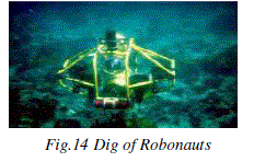 |
| Robonaut is a humanoid robotic development project conducted by the Dextrous Robotics Laboratory at NASA's Johnson Space Center (JSC) in Houston, Texas. Robonaut differs from other current space-faring robots in that, while most current space robotic systems (such as robotic arms, cranes and exploration rovers) are designed to move large objects, Robonaut's tasks require more dexterity[5]. The core idea behind the Robonaut series is to have a humanoid machine work alongside astronauts. Its form factor and dexterity are designed such that Robonaut can use space tools and work in similar environments suited to astronauts. One of the most interesting things about space travel is the drama. Human beings place themselves into amazing vehicles and travel into a completely hostile environment that is almost beyond imagination, and then describe their experiences for us in words and pictures. Landing on the moon would not have been quite the same without the astronauts providing us with words to go along with grainy black and white pictures of the lunar landscape. However, the problem with human space exploration is that the human body is too fragile for the harsh conditions of space. We have learned that space travel can take its toll on astronauts. Temperatures in space can swing from 248 degrees Fahrenheit (120 degrees Celsius) to -148 F (-100 C). There also isn't the Earth's atmosphere to shield us from the sun's radiation. In order to survive, astronauts must wear bulky space suits that cost about $12 million each. Space suits are not practical for an emergency situation. NASA has recognized the frailty of our bodies and is preparing a new breed of astronauts to perform some of the more difficult tasks in space. These new space explorers won't need space suits or oxygen to survive outside of spacecraft. These Astronauts are called Robonauts which will assist humans in future space applications. |
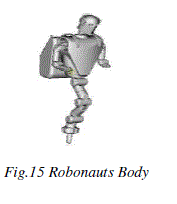 |
| The individual parts of a Robonaut are: |
| • Head |
| • Torso |
| • Legs |
| • Arms |
| • Hands |
CONCLUSION AND FUTURE SCOPE |
| The design of the control system with the use of not yet developed actuators is the most relevant part of the design process proposed .The study of the human hand plays an important role in the design of anthropomorphic architectures since it presents successful versatility, flexibility and manipulation capabilities. The present sensor system can be replaced by sophisticated sensors in order to increase the accuracy of the system. |
References |
|