INTRODUCTION
|
| Magnetic levitation (maglev) technology is mostly used in different fields such as high speed trains [1], magnetic bearings [2],and photolithography steppers for reducing friction due to mechanical contact, for low maintenance cost, and reaching high precision positioning [3]. . Commonly, magnetic levitation techniques are divided into two types: electrodynamics suspension (EDS) and electromagnetic suspension (EMS). EDS systems are generally called as “repulsive levitation”, and the sources for levitation are from superconductivity magnets / permanent magnets. Another type, electromagnetic suspension systems are generally expressed as “attractive levitation”, and this magnetic levitation force is completely unstable because of that the control problem becomes more complex. In this paper, the EMS plan is used for the basic levitation force of a linear magnetic levitation rail system, and the respective levitated positioning and the major objective of stabilizing control of magnetic levitation control system of manipulating through man model-free control schemes. The absence of contact in these systems reduces noise, component wear, vibration, and maintenance costs [5]. However, they are nonlinear and have unstable dynamics and proper performance of these Systems greatly depend on their control strategy. |
Electromagnetic Suspension
|
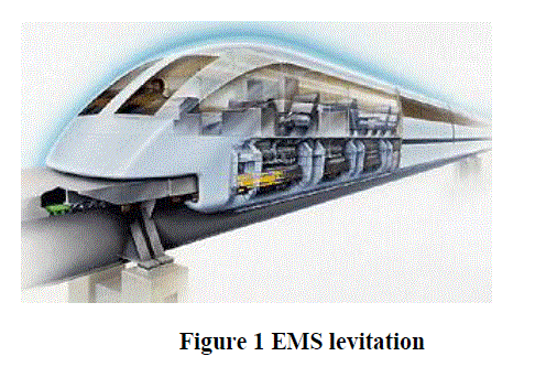
| The EMS is an attractive force levitation system where electromagnets on the vehicle interact with and are attracted to ferromagnetic rails on the guide way. The inherently unstable attractive magnetic force must be continuously and quickly adjusted by servo control of the current in the magnetic winding. Otherwise, the suspended vehicle would rapidly crash. Because an EMS system usually operates with small air gaps (10 mm), maintaining control becomes more difficult as the speed becomes higher. However, an EMS system is able to levitate by itself at zero or low speeds, since the attractive force is independent of the speed. |
| Figure 1 shows the levitation technology used in Trans rapid maglev trains. It uses a T-shaped steel guideway upon which ride vehicles with J-shaped extensions that wrap around the guide way. The support magnet levitates the train and the guidance magnet keeps the train cantered on its track. This levitation technology is favourable for high-speed operation because levitation and guidance do not interface with each other. |
 |
Electrodynamic Suspension
|
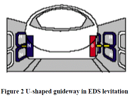
| The EDS levitation technologies may be divided into two types: the superconducting magnet type and the permanent magnet type. The design uses U-shaped elevated guideways with sidewalls containing levitation coils, some below and some above the level of the superconducting magnets on the maglev vehicles (see in Figure 2). As the train passes the superconducting magnets, an electric current is induced in the coils. This temporary current creates a temporary magnetic field that either has repulsive interactions with the superconducting magnets (coils below) or attractive interactions (coils above), resulting in a net upward force that levitates the train. The coils are also arranged such a way that any lateral movement by the train creates repulsive forces on either side of the train, thereby keeping the train centred on the track. An EDS system is stable magnetically, and it is unnecessary to control the air gap (around 100 mm). The large air gap between the vehicle and guideway means that the system is reliable for different variation of loads. Therefore, an EDS system is highly suitable for high-speed operation. |
 |
Inductrack
|
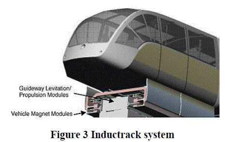
| Figure 3 shows the basic composition of an Inductrack system [5]. In this method, the permanent magnets are set up on the car, and the shorted coils on the ground. The permanent magnets on the vehicle side are positioned continuously in the direction of the magnetic poles. In addition, the shorted coils on the ground side are positioned so that they form a chain along the longitudinal direction of the magnetic field created by the coils on the vehicle side, and they are closely packed in that direction. When the train is in motion, the magnetic field from these magnets induces repelling currents in a closed-pack array of shorted conducting circuits in the track. |
 |
POSSIBLE CONTROL METHODS
|
PID Control
|
| The PID control method has advantages like simple control structure and ease of design. EMS strategy and LIM are utilized for the fundamental levitation and propulsion forces of a linear maglev rail system. A PID control system is designed to achieve the stable balancing of the maglev platform in practical applications. |
Robust Control
|
| There exist many uncertainties in maglev systems, such as parameter perturbation, unmodeled dynamics, and external disturbances.Robust control methods, such as H2 and H∞ control, present better performance compared to classical control methods. Weighting functions are employed in to attenuate the resonance peak at low frequencies in the closedloop system. The controller obtained in has a lead-lag phase characteristic, and phase lead occurring in low frequencies produces closed-loop stability. |
Intelligent Control
|
| Since maglev systems are highly nonlinear, intelligent control methods, such as neural network, fuzzy logic, and genetic algorithm are used to capture the dynamic behaviour and to achieve high- performance gap control. In , neuralfuzzy inference networks are used to capture the dynamic behaviour of a maglev vehicle. It is observed that the closedloop maglev system is entirely robust to an external disturbance. |
SYSTEM MODEL
|
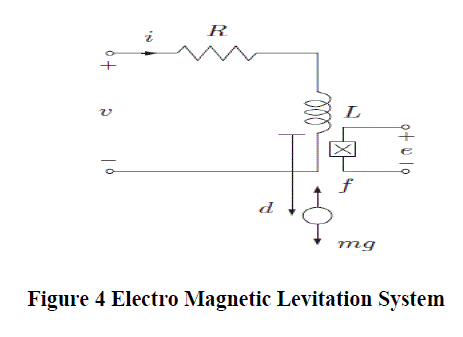
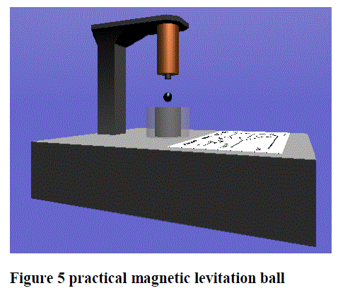
| The model of the electromagnetic levitation system is shown in Figure 4, where, m is the mass of the levitating magnet, g is the acceleration due to gravity, d is the vertical position of the levitating magnet measured from the bottom of the coil, f is the force on the levitating magnet generated by the electromagnet and e is the voltage across the Hall effect sensor. |
 |
| The force applied by the electromagnet on the levitating magnet can be closely approximated as |
 |
| The voltage across the Hall effect sensor induced by the levitating magnet and the coil can be closely approximated as |
 |
| where α, β and γ are constants that depend on the Hall effect sensor used as well as the geometry of the system and n is the noise process that corrupts the measurement. |
| Let |
 |
| be the state of the system, z = d be the controlled output, y = e be the measured output, u = v be the control input and w = n be the disturbance/noise input, the standard state equation description of the system can be written as |
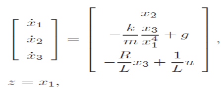 |
 |
| The Jacobian linearization of the system about the equilibrium point is |
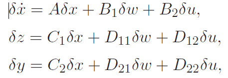 |
 |
| where, |
 |
| Then the system is |
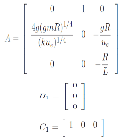 |
| where |
 |
| The transfer matrix of the linearized system is |
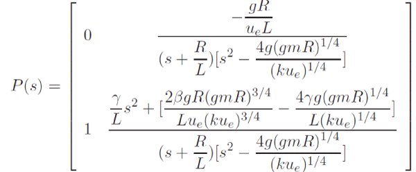 |
| Where, ΔZ(s), ΔY (s), ΔW(s) and ΔU(s) are the Laplace transforms of δ z(t), δ y(t), δ w(t) and δ u(t), respectively. In this derivation, the back emf induced by the moving levitating magnet is ignored as it is very small. If the Hall effect sensor is located below the levitating magnet, then γ is also very small and it can also be neglected. The values of these coefficients are as follows: Designed controller will have steady state error. Therefore, an integral controller is employed to overcome this problem. The gain of integral controller should be regulated according to the desirable performance. |
SIMULATION & RESULTS
|
 |
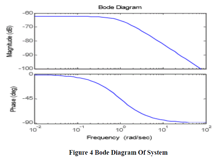
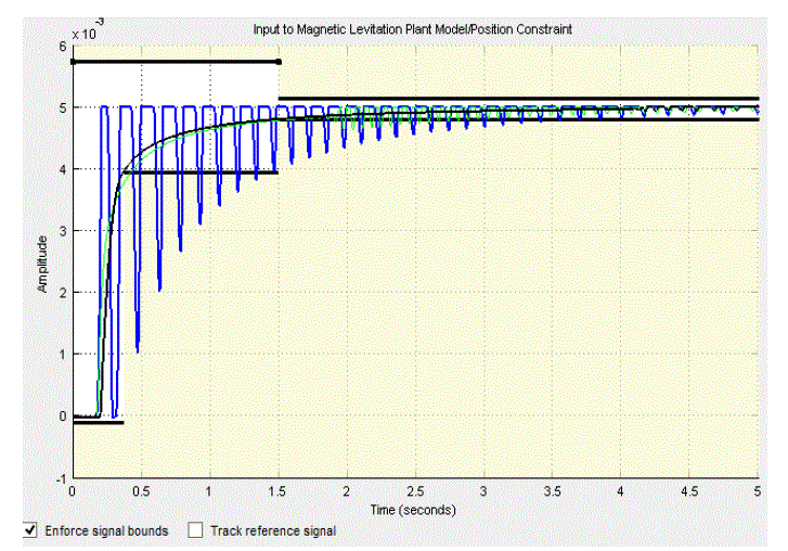
| A controller is designed for an EMS with specifications listed in table.1 and its uncontrolled Bode diagram is shown in Figure 4. It is clear from this diagram that the uncontrolled system is unstable. The value of integral controller gain is selected by try and error method. However, it can be incorporate in state feedback and calculated as optimal gain. The dynamic performance of the EMS is then simulated under the proposed control system. |
 |
 |
 |
 |
CONCLUSION
|
| One of advantages of this controller rather than previous presented methods is this that all possible errors of desirable air gap can be ruined when vast change or disorder accrued by choosing an integral controller .Also integral portion changes have been considered and it has been showed that correct choosing of integral portion can decrease the time necessary for steady state mode. Also correct choosing of integral portion helps to decrease system time reaching to stability mode. |
| These low-cost magnetic suspension kits provides with an open- ended design problem. The performance of the basic system is designed to be inadequate, allowing students to apply their knowledge to implement improvements in sensors, magnetics, power electronics, and compensation electronics. |
| |
References
|
- Yamamura, S., “Magnetic levitation technology of tracked vehicles: present status and prospects”, IEEE Transactions on Magnetics, 12(6), pp. 874-878, 1976.
- Jezerink K., Rodic M., Sabanovic A., “Sliding mode application in speed senseless torque control of an induction motor”. Proc. 15Ih IFAC world congress.Barcelona, Spine, July, 2002.
- Huixing Chen, AmingHao and Zhiqiang Long, “The controller design and performance index analysis of Maglev train's suspension system,” in 2005, vol .27, no. 2, pp.96-101
- “Proc. Of the 5th world congress on Intelligent Control and Automation”, China, 2004, pp. 596-599.
- Liu D S, Li J, Zhang K. “The design of the nonlinear suspension controller for ems maglev train based on feedback linearizati on”. Journal of National University of Defence Technology, 2005,vol .27,no. 2,pp.96-101
- F.-J. Lin and P. H. Sheen, “Robust fuzzy neural network sliding-mode control for two-axis motion control system,”IEE Transe.Ind.Electron.,vol. 53, no. 4, pp. 1209–1225, Aug. 2006.
- N F Al-Muthairi and M Zribi. “Sliding Mode Control of a Magnetic Levitation System”, Mathematical Problems in Engineering, Vol. 2, pp. 93–107, 2004.
- mariaHypiusova and Jakubosusky “PID controller design for magnetic levitation model” International conference cybernetics and information , pp.1-7, February 2010
- C. T. Lin and C. S. George Lee, “Neural Fuzzy Systems. NJ”: Prentice-Hall, 1996.
- D.-S. Liu, J. Li and W.-S. Chang, “Internal model control for magnetic suspension systems,” in Proceedings of the Fourth International Conference on Machine Learning and Cybernetics, Guangzhou, 18-21 August 2005, pp. 482-487
- Y. G. Leu, W. Y. Wang, and T. T. Lee, “Robust adaptive fuzzy-neural controllers for uncertain nonlinear systems,” IEEETrans. Robot.Automat., vol. 15, no. 5, pp. 805-817, Oct. 1999.
- F. Zhang and K. Suyama, “Nonlinear feedback control of magnetic levitating system by exact lin- earization approach”, Proc. 4th IEEE Conference on Control Applications, (New York), Sep- tember 1995, pp. 267–268.
- Z.-J. Yang and M. Tateishi,”Robust nonlinear control of a magnetic levitation system via backstep- ping approach”, Proc. 37th SICE Annual Conference (SICE ’98), (Chiba, Japan), July 1998, pp. 1063–1066
|