In the present scenario we are facing power failure at regular intervals of time. There are n number of reasons for the power failure. Out of which some reasons are studied in this article which are frequently causing power failure. Many power problems originate in the commercial power grid, because of thousands of miles of transmission lines, is subject to weather conditions such as hurricanes, lightning storms, snow, ice, and flooding along with equipment failure, traffic accidents and major switching operations. Also, power problems affecting today’s technological equipment are often generated locally within a facility from any number of situations, such as local construction, heavy start-up loads, faulty distribution components, and even typical background electrical noise. A communication mistake can have expensive consequences when the wrong power correction device is purchased for your needs, which includes downtime, lost wages, or even equipment damage. So, in this article different parameters which are responsible for problem are studied.
Keywords |
| Interruption, Sag, Voltage, Current, Frequency, Transients, Corona |
INTRODUCTION |
| In the present scenario power system is suffering from different drawbacks which are affecting
the power quality of the generated power. In the present paper different factors affecting the power system
are studied. |
INTERRUPTION |
| The causes of interruptions is caused due to damage of supply grid , such as lightning strikes, animals,
trees, vehicle accidents, destructive weather equipment failure, or a basic circuit breaker tripping. An
interruption, whether it is instantaneous, momentary, temporary, or sustained, can cause disruption,
damage, and downtime, from the domestic user up to the commercial user. A home, or small business
computer user, could lose valuable data when there is loss of power to their equipment. In case of
Industrial processes suddenly from an interruption, it can cause equipment damage, as well as the cost
associated with downtime, cleanup, and restart. So, efforts must be done in a continuous for the
elimination of interruption. Good design and maintenance of utility systems are, of course, essential. This
also applies to the industrial customer's system design, which is often as extensive and vulnerable as the
utility system. |
 |
VOLTAGE FLUCTUATIONS |
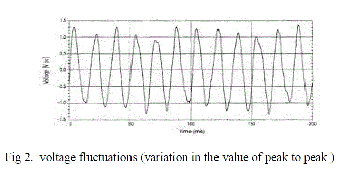
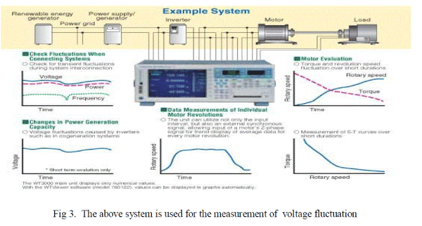
| Voltage fluctuations are changes or swings in the steady-state voltage above or below the designated
input range for a piece of equipment. Fluctuations include both sags and swells.
Humans can be sensitive to light flicker caused by voltage fluctuations. Generally speaking, flicker can
significantly impair our vision and cause general discomfort and fatigue. The physiology of this
phenomenon is complex. In general terms, flicker affects our vision process and brain reaction, almost
always producing discomfort and deterioration in work quality. In some situations, it can even result in
workplace accidents because it affects the ergonomics of the production environment by causing operator
fatigue and reduced concentration levels. The fluctuations are mainly caused due to large equipment startup
or shutdown, sudden change in load, improper wiring or grounding. Due to voltage fluctuations the
equipment like computers, fax machines, variable frequency drives, machines, motors will get damaged.
As a result, equipment shutdown, flickering lights, reducing motor life etc occurs. Voltage fluctuations can
be reduced by using standby generators, stabilizers and UPS etc. |
 |
 |
 |
SAG |
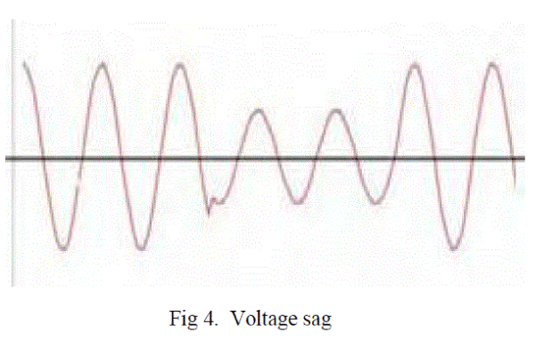
| Monitoring Electric Power Quality, is a decrease in RMS voltage at the power frequency for durations
from 0.5 cycles to 1 minute, is said to be the remaining voltage. The measurement of a voltage sag is
stated as a percentage of the nominal voltage, it is a measurement of the remaining voltage and is stated as
a sag to a percentage value. Thus a voltage sag to 60% is equivalent to 60% of nominal voltage, or 288
volts for a nominal 480 Volt system. |
 |
| Voltage sags can occur on utility systems both at distribution voltages and transmission voltages.
Voltage sags that occur at higher voltages will normally spread through a utility system and will be transmitted to lower voltage systems via transformers. Voltage sags can be created within an industrial
complex without any influence from the utility system. These sags are typically caused by starting large
motors or by electrical faults inside the facility. If electrical equipment fails due to overloading, cable
faults etc., protective equipment will operate at the sub-station and voltage sags will be seen on other
feeder lines across the utility system. Thunderstorms and lightning strikes cause a significant number of
voltage sags. If lightning strikes a power line and continues to ground, this creates a line-to-ground fault.
The line to ground fault in turn creates voltage sag and this reduced voltage can be seen over a wide area.
Note the lightning strike to ground causes voltage sags on all other lines. The sag is caused by different
reasons like pollution, birds and animals, vehicle problem, construction activity etc. The most common
voltage sags, over 70%, are single phase events which are typically due to a phase-to-ground fault
occurring somewhere on the system. This phase-to-ground fault appears as a single phase voltage sag on
other feeders from the same substation. Typical causes are lightning strikes, tree branches, animal contact
etc. It is not uncommon to see single phase voltage sags to 30% of nominal voltage or even lower in
industrial plants. Two-phase, phase-to-phase sags may be caused by tree branches, adverse weather,
animals or vehicle collision with utility poles. The two-phase voltage sag will typically appear on other
feeders from the same substation. A brownout is an intentional drop in voltage in an electrical power supply
system used for load reduction in an emergency. The reduction lasts for minutes or hours, as opposed to
short-term voltage sag or dip. The term brownout comes from the dimming experienced by lighting when
the voltage sags. A voltage reduction may be an effect of disruption of an electrical grid, or may
occasionally be imposed in an effort to reduce load and prevent a blackout. |
WAVEFORM DISTORTION |
| Here are 5 primary types of waveform distortion: |
| A. DC Offset |
| B. Harmonics |
| C. Interharmonics |
| D. Notching |
| E. Noise |
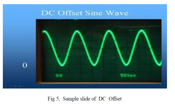
| A. DC Offset |
| DC Offset is often introduced into the AC distribution system upon the failure of a rectifier or AC/DC
power supply. These failures can cause DC to traverse the AC line and add unwanted current to our on line
devices. Overheating and saturation of transformers can also occur, creating additional waveform
distortion and instability. To resolve this problem the faulty equipment must be replaced. |
 |
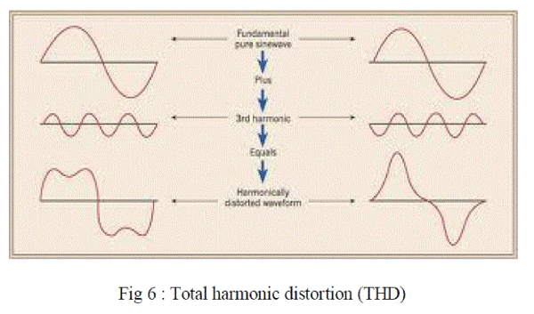
| B. Harmonic Distortion |
| Harmonic distortion is the corruption of the fundamental sine wave at frequencies that are multiples of
the fundamental. (e.g., 180Hz is the 3rd harmonic of a 60Hz fundamental frequency;
3x60=180) Symptoms of harmonic problems include overheated transformers, neutral conductors, circuit
breaker tripping and loss of synchronization. The common cause of harmonic distortion is switch mode
power supplies and other non-linear loads and capacitive designs commonly used in today’s electronic
equipment. In order to mitigate this problem the size of the neutral conductors should be over sized and/or
install K-rated transformers and harmonic filters. |
 |
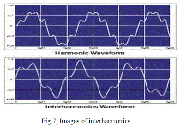
| C. Interharmonics |
| Interharmonics are a type of waveform distortion usually the result of a signal imposed on the supply
voltage by electrical equipment such as static frequency converters, induction motors, and arcing
devices. A symptom of interharmonics is visual flickering of displays and lights as well as causing
possible heat and communication interference. To reduce interharmonics UPS Systems and Line
conditioners. |
 |
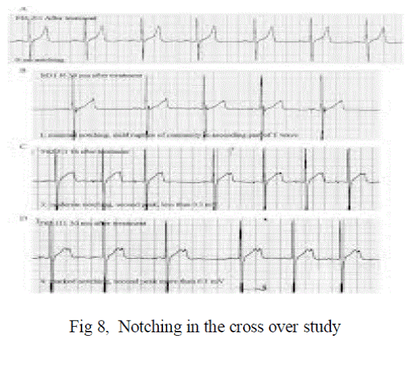
| D. Notching |
| Notching is a periodic voltage disturbance caused by electronic devices such as variable speed drives,
light dimmers and arc welders under normal operation. Usual consequences are system halts, data loss and
data transmission errors. To reduce notching the load has to be removed away from the equipment causing
the problem or install a filter or UPS Systems and Line Conditioners. |
 |
| E. Noise |
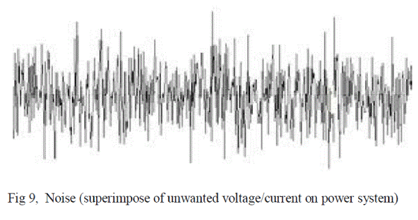
| Noise is the unwanted voltage or current superimposed on the power system voltage or current
waveform. Noise can be generated by power electronic devices, control circuits, arc welders, switching
power supplies etc... Poor grounded sites make the systems more susceptible to noise and can cause data
errors, hard disk and component failures as well as video display distortion. There are many approaches to
controlling noise and occasionally several are required. Some methods include isolating the load via a UPS
Systems or Line conditioners. The other solution to reduce noise is to install a grounded isolation
transformer or relocate the load away from the interference source. The noise can also be reduced by
installing noise filters and cable shielding. |
 |
TRANSIENTS |
| A transient is a high voltage spike caused by external or internal transient sources. A transient is a high
voltage spike of less than 10 microseconds in duration. Transients in power lines may have voltage spikes
up to 6,000 volts, and it is not unusual that spikes in commercial industrial circuits excess 1,000 volts.
High voltage transients follows the path of least resistance to the ground, creates a damaging heat in the
circuit components and causing malfunctions and failure. External transients at high voltage caused by
lightning hitting the power lines are reduced through the distribution transformers by a factor typical 1 to
6. Since the transients caused by lighting may be extremely high - more than 50,000 volts - the resulting
transients after the transformers in the distribution system may be very high when they reach the internal
circuit. Switching on and off of motors in the internal circuit can cause transients up to 2,500 volts. This is
known as internal transient. |
 |
OVER VOLTAGE |
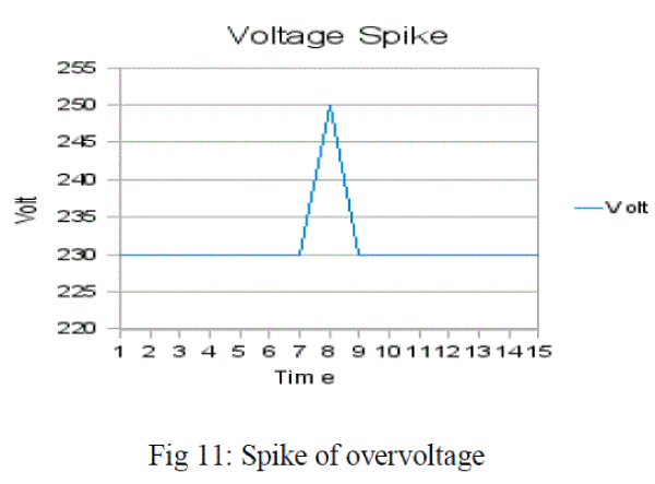
| A voltage greater than that at which a device or circuit is designed to operate. Also known as over
potential. The amount by which the applied voltage exceeds the Geiger threshold in a radiation counter
tube. The difference between electrode potential under electrolysis conditions and the thermodynamic
value of the electrode potential in the absence of electrolysis for the same experimental conditions. Is also
known as over potential. |
 |
CONCLUSION |
| So, by reducing the above parameters power system can be protected. A voltage distribution system
with local generation which is synchronized with the grid. During grid disturbances, the local plant
generators have to be isolated from the grid. The power system is protected from lighting by using
shielding by earth wires, proper earthing of transmission towers, and surge arrestors like ZnO
varistor. |
| |
References |
- Amy Abel and Larry Parker. Electricity: the Road to Restructuring (CRS Issue Brief for Congress) Updated August 12, 2003. 19 p. [PDF Format: 392 KB/ 19 p.
- Amy Abel. Government Activities To Protect the Electric Grid (CRS Report for Congress) October 20, 2004. 6 p. [PDF Format: 40 KB/ 6 p.
- Stoft, Steven. Power system economics: designing markets for electricity. Piscataway, NJ : IEEE Press ; New York : Wiley- Interscience, 2002. 468 p. Catalog record
- Jamison, Mark A. Industry structure and pricing : the new rivalry in infrastructure. Boston : Kluwer Academic, c2000. 207 p. Catalog record
- William Sweet, "Restructuring the thin-stretched grid," in IEEE Spectrum, June 2000, pp. 43-49. Publisher's Abstract Catalogue record
- Massoud Amin, "Toward self-healing energy infrastructure systems," in IEEE Computer Applications in Power, January 2001, pp. 20-28. Publisher's Abstract Catalogue record
- "Power system basics for business professionals in our industry," in IEEE Power & Energy, January-February 2003, pp. 16-20.Publisher's Abstract Catalogue record
|