This paper describes various types of digital transducers. It also tells their principles of operation and describes how they are applicable in fields. These transducers are nowadays very popular as they produces digital signal as output which can be easily read by digital devices, and there is no such requirement of analog to digital conversion for further analysis of measured quantity.
Keywords |
| Revolution per minute, Programmable Logic Controller, wheel impulse generators |
INTRODUCTION |
| A transducer measures physical quantities and transmits the information as coded digital signals rather than as
continuously varying currents or voltages. Any transducer that presents information as discrete samples and that does
not introduce a quantization error when the reading is represented in the digital form may be classified as a digital
transducer. |
| Most transducers used in digital systems are primarily analogue in nature and incorporate some form of
conversion to provide the digital output. Many special techniques have been developed to avoid the necessity to use a
conventional analogue- to-digital conversion technique to produce the digital signal. This article describes some of the
direct methods which are in current use of producing digital outputs from transducers. |
| Some of the techniques used in transducers which are particularly adaptable for use in digital systems are introduced.
The uses of encoder discs for absolute and incremental position measurement and to provide measurement of angular
speed are outlined. The application of linear gratings for measurement of translational displacement is compared with
the use of Moire fringe techniques used for similar purposes. Synchro devices are briefly explained and the various
techniques used to produce a digital output from synchro resolvers are described. Brief descriptions of devices which
develop a digital output from the natural frequency of vibration of some part of the transducer are presented. Digital
techniques including vortex flowmeters and instruments using laser beams are also briefly dealt with. Some of them are
as follows: |
| 1. Shaft Encoders |
| 2. Digital Resolvers |
| 3. Digital Tachometers |
| 4. Hall Effect Sensors |
| 5. Limit Switches |
| With computers being used more often in measurement applications, it is attractive to have sensors that can produce
digital output directly. Digital “sensors” or transducers generate discrete-level output signals such as pulse trains or
encoded data that can be read directly by a control processor. Motion is easily detected using different “digital” sensing
mechanisms, but using this as a basis it is possible to build digital sensors to detect force, pressure, torque, etc. A
counter is commonly used to count output pulses or clock cycles over a pulse duration. |
ADVANTAGES OF DIGITAL TRANSDUCERS |
| It provides ease of generating, manipulating, and storing digital signals. It performs measurement with absolute
accuracy and discrimination. It supports relative immunity of a high-level digital signal to external disturbances (noise),
especially in transmitting signals over long distances. It gives simplified data presentation. |
TYPES OF DIGITAL TRANSDUCERS |
| 1. Shaft Encoders: An encoder is a device that provides a coded reading of a measurement. A Shaft encoders can be
one of the encoder that provide digital output measurements of angular position and velocity. This shaft encoders are
excessively applicable in robotics, machine tools, mirror positioning systems, rotating machinery controls (fluid and
electric), etc. |
| Shaft encoders are basically of two types-Absolute and Incremental encoders. |
Absolute and incremental encoders: |
| An "absolute" encoder maintains position information when power is removed from the system. The position of the
encoder is available immediately on applying power. The relationship between the encoder value and the physical
position of the controlled machinery is set at assembly; the system does not need to return to a calibration point to
maintain position accuracy. An "incremental" encoder accurately records changes in position, but does not power up
with a fixed relation between encoder state and physical position. Devices controlled by incremental encoders may
have to "go home" to a fixed reference point to initialize the position measurement. A multi-turn absolute rotary
encoder includes additional code wheels and gears. A high-resolution wheel measures the fractional rotation, and
lower-resolution geared code wheels record the number of whole revolutions of the shaft. |
| An absolute encoder has multiple code rings with various binary weightings which provide a data word representing the
absolute position of the encoder within one revolution. This type of encoder is often referred to as a parallel absolute
encoder. |
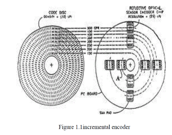
| An incremental encoder works differently by providing an A and a B pulse output that provide no usable count
information in their own right. Rather, the counting is done in the external electronics. The point where the counting
begins depends on the counter in the external electronics and not on the position of the encoder. To provide useful
position information, the encoder position must be referenced to the device to which it is attached, generally using an
index pulse. The distinguishing feature of the incremental encoder is that it reports an incremental change in position of
the encoder to the counting electronics. |
 |
 |
1.1 Encoder Applications |
Examples of uses for an industrial rotary encoder |
| Encoders may be used in a wide variety of applications. They can be used as feedback devices for motor speed control,
length measurement, position and input for rate and speed indication and control. A few of the specific areas where
encoders are used are listed below followed by some practical examples. |
| • Door control devices |
| • Lens grinding machines |
| • Converting machinery |
| • Labeling machines |
| • Drilling machines |
| • Mixing machines |
| • Medical equipment |
| • Robotics |
| • Length Measurement |
| • Bottling machines |
| • Telescopes |
| • Conveyors |
| • Process lines |
| • CNC machines |
| • Automatic welding |
| • Bar code readers |
| • Rolling mills |
| • Elevators |
| • Radar |
| • Winding machines |
| • Nuclear processes |
| • Wind turbines |
| Following are a few practical examples of common encoder installations within these and other areas. |
Applications Examples |
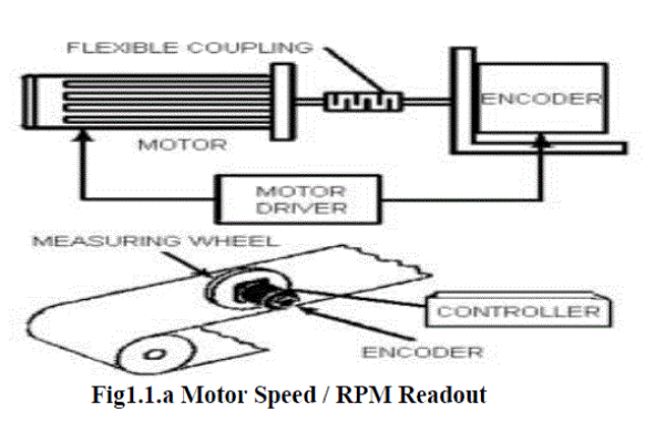 |
| Motor Speed / RPM Readout is the most common way that encoders are used. In this type of application, the encoder
is mounted directly to the end of a motor via a shaft. The critical parameter of measurement is motor speed whereby the
encoder provides feedback to a drive, so that the drive can verify that the speed and direction is correct. This team
effort between the drive and the encoder ensures that whatever the motor is driving runs safely and smoothly and does
not run out of control or erratically in applications where precise speed is a requirement. As the second diagram shows
speed can also be monitored and controlled by a simple measuring wheel running on the material. In this case the motor
would be coupled to a drive roller. Hollow shaft encoders mounted over the motor shaft are frequently used thereby
eliminating the need for a flexible coupling and saving space. |
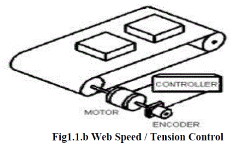 |
| Web Speed / Tension Control is an application in which an encoder is mounted to a motor as well as a tension roller.
Any unevenness in the rotating speed of the tension roller is fed to a controller which sends a signal to the drive motor
to adjust in order to maintain an even tension proportion between the web roller and drive motor. Maintaining optimal
web tensioning is critical in assembly and conveyor applications or in roll tensioning applications designed to prevent
tearing, backlash or other potential injury to machine operators |
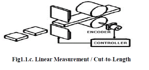 |
| Linear Measurement / Cut-to-Length is a form of linear measurement whereby an encoder is mounted on a lead
screw or measuring wheel to prevent a user from having to physically measure (using a tape measure or inaccurate
hand mark or eye estimate) a length of material before it is cut. Since an encoder delivers a fix number of pulses in a
revolution, a device can be scaled to increment at a designated length per pulse. This device may be a preset counter or
PLC that in turn has a relay output that can be set to operate when the desired length is reached to ensure a precise and
accurate cut every time. |
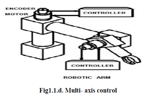 |
| Multi- axis control can be achieved using incremental or absolute encoders. They need to be high resolution accurate
devices and are used in a variety of automated applications in manufacturing and research
Radar antenna, robotic arms or satellite dish rotation are good examples of this type of application. |
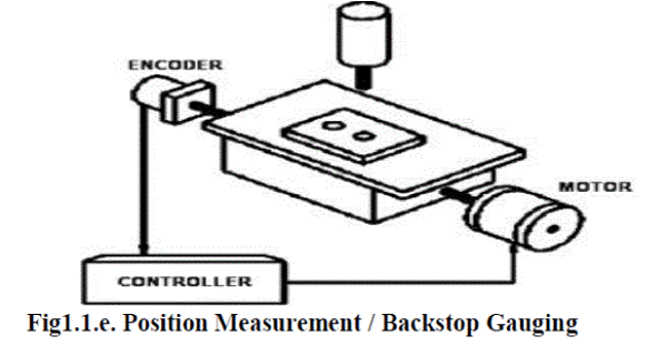 |
| Position Measurement / Backstop Gauging this position measurement application is similar to a cut to length
application whereby the encoder is used to make sure that the unit, typically a machine tool, does not exceed a preset
position or direction of travel. Very often, this is combined with a determination of the speed of travel of the table, tool
head, or similar component to ensure that the machine does not over travel. Though limit switches can be used in
backstop applications, encoders are more shock resistant and tend to last longer. |
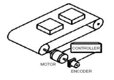 |
Fig 1.1.f. Position Measurement / Conveying |
| Position Measurement / Conveying is another common industry application where encoders are widely used to
monitor and control conveyor speed and position. Similar to a motor feedback application, encoders are attached to a
motor, to intermediate axle shafts, or to both. The critical parameters of measurement are motor speed and incremental
movement. In this case the encoder can control both the conveyor speed and position |
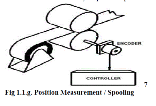 |
| Position Measurement / Spooling is another application where encoders are advantageous. The encoder is mounted to
the shaft of a spool, and the connected controller keeps track of the length and speed of the take up material being
spooled based on feedback from the encoder. |
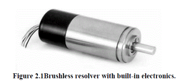
| 2. Digital Resolvers: Digital resolver is a compact, low-cost angular position transducer with DC input and digital
output. No external circuitry is required – simply energize with ±5 VDC and obtain 12-bit serial data for direct
computer interface, or the A Quad B and North Marker outputs of an incremental encoder. Brushless resolvers are
superior to encoders in terms of ruggedness, size, accuracy and resolution. Resolvers perform efficiently under
temperature extremes, humidity, shock and vibration. |
 |
| 2.1 Applications: Typical applications of Digital Resolvers under situations where precise position data is required for
computer input. Some of the areas of its applications are: |
| • Position and velocity sensing |
| • Brushless DC servo commutation |
| • Robotics and factory automation |
| • CNC machine tools |
| • Material handling |
| • Medical devices |
2.2 Features |
| • Heavy-duty brushless resolver |
| • Totally digital input / output |
| • Absolute position data output |
| • Good resolution standard |
| • Maximum system error of ±15 arc minutes |
| • Incremental encoder with A Quad B and North Marker outputs |
| • High readout rate |
| • Mechanical modifications to order |
| 3. Digital Tachometers: A tachometer (revolution-counter, Tach, rev-counter, RPM gauge) is an instrument measuring
the rotation speed of a shaft or disk, as in a motor or other machine.[1] The device usually displays the revolutions per
minute (RPM) on a calibrated analogue dial, but digital displays are increasingly common. The word comes from
Greek Ταχος, tachos, "speed", and metron, "to measure". |
| Digital tachometers are particularly suitable for the precision measurement and monitoring of all time related
quantities, which are able to be converted into a proportional frequency using appropriate sensors Time-related
quantities include rotational and linear velocity, flow rate and related quantities. The instrument can be programmed to
measure absolute values ratio, or proportional difference. The proportional frequency is generally produced by a
magnetic wheel on the shaft, which is scanned by a radial mounted impulse sensor for control applications, a high
resolution pick-up can be coupled directly to the motor shaft. |
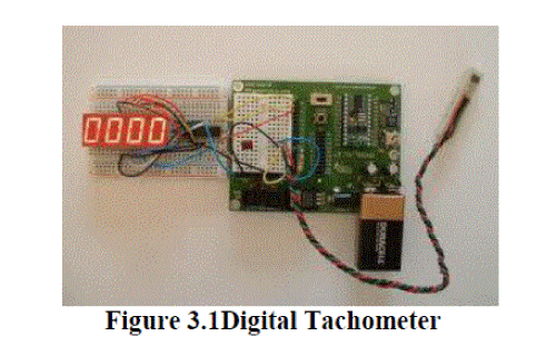 |
| A digital Tachometer is digital device which measure the speed of a rotating object. A rotating object can be a ceiling
fan, it can be a car tyre etc. In this meter we just take no. of pulses for one minute then divide by 60, this gives the no.
of pulses per min. And its reciprocal i.e. time for these pulses will be 60/N, where N are pulses for one minute. Then
we apply these pulses (which in fact decide open gate time for counting the pulses of a clock signal). Now the no. of
pulses of clock signal which are counted by a counter and divide by the open gate time (60/N) gives frequency of the
rotating object. Since this frequency i.e. no. of pulses so this the original speed (rpm) of a rotating shaft. |
3.1 Applications: |
i) Traffic Engineering |
| Tachometers are used to estimate traffic speed and volume (flow). A vehicle is equipped with the sensor and conducts
"tach runs" which record the traffic data. These data are a substitute or complement to loop detector data. To get
statistically significant results requires a high number of runs, and bias is introduced by the time of day, day of week,
and the season. However, because of the expense, spacing (a lower density of loop detectors diminishes data accuracy),
and relatively low reliability of loop detectors (often 30% or more are out of service at any given time), tach runs
remain a common practice |
| ii) In trains and light rail vehicles: Speed sensing devices, termed variously "wheel impulse generators" (WIG), speed
probes, or tachometers are used extensively in rail vehicles. Common types include opto-isolator slotted disk sensors
and Hall Effect sensors. Hall Effect sensors typically use a rotating target attached to a wheel, gearbox or motor. This
target may contain magnets, or it may be a toothed wheel. The teeth on the wheel vary the flux density of a magnet
inside the sensor head. The probe is mounted with its head a precise distance from the target wheel and detects the teeth
or magnets passing its face. One problem with this system is that the necessary air gap between the target wheel and the
sensor allows ferrous dust from the vehicle's under-frame to build up on the probe or target, inhibiting its function. |
| iii) In analogue audio recording In analogue audio recording, a tachometer is a device that measures the speed of audiotape as it passes across the head.
On most audio tape recorders the tachometer (or simply "tach") is a relatively large spindle near the ERP head stack,
isolated from the feed and take-up spindles by tension idlers. |
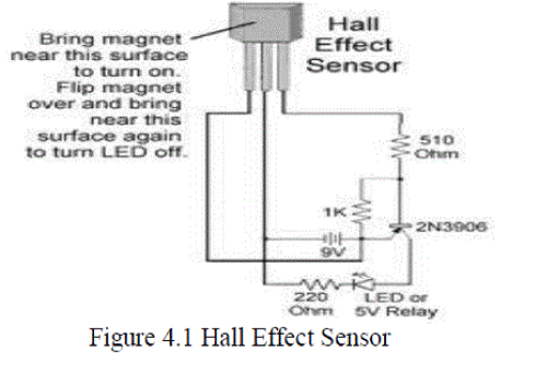
| 4. Hall Effect Sensors: A Hall Effect sensor is a transducer that varies its output voltage in response to a magnetic
field. Hall Effect sensors are used for proximity switching, positioning, speed detection, and current sensing
applications. |
| In its simplest form, the sensor operates as an analog transducer, directly returning a voltage. With a known magnetic
field, its distance from the Hall plate can be determined. Using groups of sensors, the relative position of the magnet
can be deduced. |
| Electricity carried through a conductor will produce a magnetic field that varies with current, and a Hall sensor can be
used to measure the current without interrupting the circuit. Typically, the sensor is integrated with a wound core or
permanent magnet that surrounds the conductor to be measured. |
 |
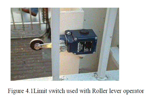
| 5. Limit Switches: In electrical engineering a limit switch is a switch operated by the motion of a machine part or
presence of an object. They are used for control of a machine, as safety interlocks, or to count objects passing a point.
Standardized limit switches are industrial control components manufactured with a variety of operator types, including
lever, roller plunger, and whisker type. Limit switches may be directly mechanically operated by the motion of the
operating lever. A reed switch may be used to indicate proximity of a magnet mounted on some moving part. The class
of proximity switches operates by the disturbance of an electromagnetic field, by capacitance, or by sensing a magnetic
field (e.g., a Hall-effect sensor). |
| Rarely, a final operating device will be directly controlled by the contacts of an industrial limit switch, but more
typically the limit switch will be wired through a control relay, a motor contactor control circuit, or as an input to a
programmable logic controller. |
 |
5.1 Types of Limit switches: |
| Limit switch performance depends on a number of factors. In addition to the operational parameters and mechanical
specifications of a machine, these factors include the size, mounting method, and force capacity of the switch, as well
as the stroke rate involved in the operating process. It is important for a limit switch’s electrical rating to match that of
the system into which it is installed in order to reduce the potential for instrument failure and ensure proper functioning.
The common types of limit switches used in industrial applications include: |
| i) Heavy-Duty Precision Oil-Tight: Also known as the Type C limit switch, this device is highly reliable due to its
long electrical and mechanical lifespan. It features a straightforward wiring arrangement and relatively easy
installation. The Type C can be equipped with a range of different head and body styles, including a more durable
design that is watertight and submersible. It is available in a standard format, as well as with specialized reed contacts. |
| ii) Heavy-Duty Oil-Tight and Foundry: When load requirements exceed the capacity range for a precision oil-tight
switch, a regular heavy-duty oil-tight model, or Type T, may be needed. It can handle operating sequences unavailable
on the Type C and can withstand high trip and reset forces. The heavy-duty foundry limit switch, or Type FT, is
commonly used in foundries and mills where Type T operating conditions are coupled with elevated temperatures and
foreign materials that may jam other types of switches. |
| iii) Miniature Enclosed Reed: This limit switch, also known as Type XA, is a smaller and less expensive device
formed from die-cast zinc. It contains a contact array featuring a hermetically sealed reed, which makes it well-suited
for applications that require a high level of contact reliability or involve environmental stresses. The switch is normally
prewired and can be placed in smaller or harder to reach areas. |
| iv)Gravity Return: The gravity return limit switch is usually employed in production line and conveyor operations
involving small, lightweight components. This type of switch relies on gravity to reset its contact switches by exerting
force on a lever arm and typically functions with a low level of torque. There are several varieties of gravity return
switches, including spring return, roller type, lever type, top push, and maintained contact designs. |
| v) Snap Switches: A snap switch is designed to instantly trigger as soon as the mechanism attached to the switch has
moved a predetermined distance, regardless of the speed at which the moving part travels. Snap switches are commonly
used in applications that require only basic contact parameters and can work with or without an operator. They are
effective in machine systems that feature short movements or a slow rate of operation. |
| |
References |
- George Albert Woolvet âÃâ¬ÃÅInstrument science and technologyâÃâ¬Ã J. Phys. E: Sci. Instrum., Vol. 15,1982. Printed in Great Britain.
- Cheng-Ta ChiangâÃâ¬Ã A CMOS phase to digital transducer for optical incremental sensorsâÃâ¬ÃÂ, Advanced Intelligent Mechatronics(AIM),IEEE/ASME conference Vol.2, 226 âÃâ¬Ãâ 229, JULY 2011.
- Richard R. RichardâÃâ¬Ã Development of an inherently digital transducerâÃâ¬Ã National Aeronautics and Space Administration, 1972.
- Kraft, Michael and Lewis, Christopher P. âÃâ¬ÃÅA Generic Approach To Closed Loop, Digital TransducersâÃâ¬Ã CoventryUniversity, School of Engineering.
- R.G. Longoria âÃâ¬ÃÅDigital Transducers and Digital Signal MeasurementâÃâ¬Ã April 18, 2000, Department of Mechanical Engineering TheUniversityof Texas at Austin.
- CP Lewis âÃâ¬Ã Control system aspects of digital transducer designâÃâ¬Ã 612 - 614 vol.4 Oct 1993.
- Yun, W., H owe, R. T. and Gray, P.R. (1992) âÃâ¬ÃÅSurface micro machined, digitally force -balanced accelerometer with integratedCMOS detection circuitryâÃâ¬ÃÂ. IEEE, 0-7803-0456X/ 9 2, 126 - 131.
- Lewis, C. P. and Hesketh, T. G. âÃâ¬ÃÅdigital current transducerâÃâ¬Ã Proc. EME, 4th European Power Electronics Conf., Vol. 3, pp. 488-490,Firenze, 1991.
|