Keywords
|
| Direct Torque Control (DTC), Fuzzy Logic Control(FLC), Induction Motor Drives (IMD), Proportional controller, Space Vector Modulation (SVM) |
INTRODUCTION
|
| Since Depenbrock and Isao Takahashi proposed Direct Torque Control for induction machines in the middle of 1980's, more than one decade has passed. The basic idea of DTC for induction motor is slip control, which is based on the relationship between the slip and electromagnetic torque. In the 1990's, DTC for Permanent Magnet Synchronous Machines was developed. Compared with Rotor Field Oriented Control, the DTC has many advantages such as less machine parameter dependence, simpler implementation and quicker dynamic torque response. There is no current controller needed in DTC, because it selects the voltage space vectors according to the errors of flux linkage and torque. |
| The scalar control is operating in steady state and controls the angular speed of current, voltage, and flux linkage in the space vectors. Thus, the scalar control does not operating in the space vector position during transient state. The vector control, which is based on relations valid for dynamic states, not only angular speed and magnitude but also instantaneous position of current, voltage, and flux linkage of space vector are controlled. In the vector control, one of the most popular control method for induction motor drives, known as Field Oriented Control (FOC) is presented by F.Blaschke (Direct FOC) and Hasse (Indirect FOC) in early 1970’s, and FOC gives high performance, and high efficiency for industrial applications . In this FOC, the motor equations are transformed into a coordinate system that rotates in synchronism with the rotor flux vector control . The FOC is good in high dynamic performance, low stator flux and torque ripples, switching frequency, and maximum fundamental component of stator current, but FOC method has some drawbacks, such as requirement of two co-ordinate transformations, current controllers, and high machine parameter sensitivity. This drawback was eliminated using the new strategies for torque and flux ripple control of IMD using DTC was proposed by Isao Takahashi and Toshihiko Noguchi, in the mid 1980’s. |
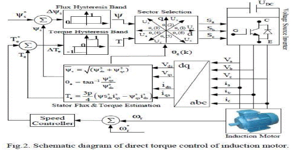
| Comparing with FOC, DTC has a simple control scheme and also very less computational requirements, such as current controller, and co-ordinate transformations are not required. The main feature of DTC is simple structure and good dynamic behavior and high performance and efficiency. The schematic diagram of conventional DTC of IMD is shown in Fig.2. |
 |
| The new control strategies proposed to replace motor linearization and decoupling via coordinate transformation, by torque and flux hysteresis controllers. This method referred as conventional DTC. In the conventional DTC has some drawbacks, such as, variable switching frequency, high torque and flux ripples, problem during starting and low speed operating conditions, and flux and current distortion caused by stator flux vector changing with the sector position , and the speed of IMD is changing under transient and dynamic state operating condition. In order to overcome with this problem, the proposed DTC with PI and FLC is using. The P controller is using for speed control in the SR loop and the FLC is using for stator flux and torque ripple reduction in the torque control loop. The conventional and proposed DTC of IMD simulation results are presented and compared. Finally the effectiveness, validity, and performance of DTC of IMD using both conventional and proposed controllers are analyzed, studied, and confirmed by simulation results and the results shows low stator flux and torque ripples, and good speed regulator of IMD with the proposed technique using MATLAB/SIMULINK. |
MODELLING OF AINDUCTION MOTOR
|
| For simplicity, the induction motor considered will have the following assumptions: |
| • Symmetrical two-pole, three phase windings. |
| • The slotting effects are neglected. |
| • The permeability of the iron parts is infinite. |
| • The flux density is radial in the air gap. |
| • Iron losses are neglected. |
| • The stator and the rotor windings are simplified as a single, multi-turn full pitch coil situated on the two sides of the air gap. |
 |
| Cross section of elementary symmetrical three phase induction motor |
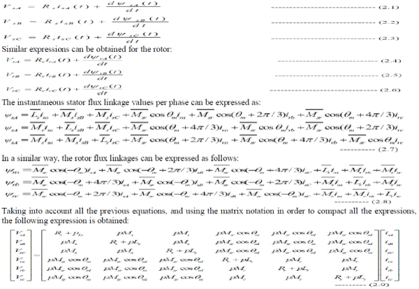
| The stator voltages will be formulated in this section from the motor natural frame, which is the stationary reference frame fixed to the stator. In a similar way, the rotor voltages will be formulated to the rotating frame fixed to the rotor. In the stationary reference frame, the equations can be expressed as follows: |
 |
MODELLING OF THE INDUCTION MOTOR USING REFERENCE FRAME
|
Applying Park’s transform:
|
| In order to reduce the expressions of the induction motor equation voltages given in equation 2.1 to equation 2.6 and obtain constant coefficients in the differential equations, the Park’s transform will be applied. Physically, it can be understood as transforming the three windings of the induction motor to just two windings, as it is shown in figure 2.2 |
 |
| In the symmetrical three-phase machine, the direct- and the quadrature-axis stator magnitudes are fictitious. The equivalencies for these direct (D) and quadrature (Q) magnitudes with the magnitudes per phase are as follows: |
 |
 |
| Where "c" is a constant that can take either the values 2/3 or 1 for the so-called non-power invariant form or the value 2 / 3 for the power-invariant form. These previous equations can be applied as well for any other magnitudes such as currents and fluxes. Applying the mentioned Park's transform. |
 |
DIRECT TORQUE CONTROL OF INDUCTION MOTOR
|
| In a dc machine, neglecting the armature reaction effect and field saturation, the developed torque is given by |
 |
| Where Ia = armature current and If = field current. |
 |
| The construction of a DC machine is such that the field ψf produced by the current If is perpendicular to the armature flux ψa, which is produced by the armature current Ia. These space vectors, which are stationary in space, are orthogonal or decoupled in nature as shown in figure 3.1. This means that when torque is controlled by controlling the current Ia, the flux ψf is not effected and we get the fast transient response and high torque/ampere ratio with the rated ψf. Because of the decoupling, when the field current If is controlled, it affects the field flux ψf only, but not the ψa flux. |
| The DC machine like performance is obtained in Direct Torque Controlled (DTC) drives. In DTC drives, the decoupling of the torque and flux components is accomplished by using hysteresis comparators which compares the actual and estimated values of the electromagnetic torque and stator flux. The DTC drive consists of DTC controller, torque and flux calculator, and a Voltage Source Inverter (VSI). |
DTC Scheme
|
| In figure 1.2 a possible schematic of Direct Torque Control is shown. As it can be seen, there are two different loops corresponding to the magnitudes of the stator flux and torque. The reference values for the flux stator modulus and the torque are compared with the actual values, and the resulting error values are fed into the two level and three-level hysteresis blocks respectively. The outputs of the stator flux error and torque error hysteresis blocks, together with the position of the stator flux are used as inputs of the look up table (see table I). |
 |
| The inputs to the look up table are given in terms of +1,0,-1 depend on weather the torque and flux errors within or beyond hysteresis bands and the sector number in which the flux sector presents at that particular instant. |
 |
| In accordance with the figure 1.2, the stator flux modulus and torque errors tend to be restricted within its respective hysteresis bands. From the schematic of DTC it is cleared that, for the proper selection of voltage sector from lookup table, the DTC scheme require the flux and torque estimations. |
RESULT AND DISCUSSION
|
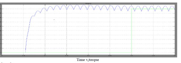
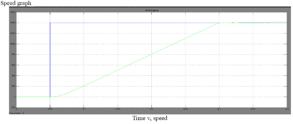
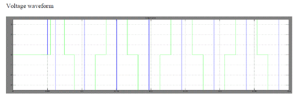
| Constant torque and flux commands of 20 Nm and 0.27Wb were used. The simulation was run at 110-V DC bus voltage. |
| The reference torque and the resulted torque is shown below Torque graph |
 |
 |
 |
 |
 |
CONCLUSION
|
| Direct Torque Control is supposed to be one of the best controllers for driving any induction motor. Its main principles have been introduced and deeply explained. It is also demonstrated in this thesis that the method of DTC also allows the independent and decoupled control of motor torque and motor stator flux. A SIMULINK/MATALB® model has been fully developed. From the results it is apparent that DTC strategy is simpler to implement than the flux vector control method because voltage modulators and co-ordinate transformations are not required. Although, it introduces some disadvantages, being the torque ripple one of the worst |
| |
References
|
- Bose, B. K.; "Power Electronics and AC Drives". Prentice-Hall. 1986.
- Mohan, Undeland, Robbins. “Power Electronics".Wiley.Second edition. 1989.
- Novotny, D. W. and Lipo, T. A. “Vector Control and Dynamics of AC Drives.” Oxford University Press Inc, New York, 1996.
- Vas, P. " Sensor less Vector and Direct Torque Control". Oxford University Press 1998.
- Paul C. Krause, Oleg Wasynczuk, Scott D. Sudhoff “Analysis Of Electric Machinery And Drives” Second Edition, IEEE Press Wiley Interscience 2002.
- Tejavathu Ramesh, Anup Kumar Panda “Direct Flux and Torque Control of Three Phase Induction Motor Drive Using PI and Fuzzy Logic Controllers for Speed Regulator and Low Torque Ripple” IEEE of 2012.
|