ISSN ONLINE(2278-8875) PRINT (2320-3765)
ISSN ONLINE(2278-8875) PRINT (2320-3765)
| K Jayashri, T Murali and K Sathish Kumar UG Student , Department of Electrical and Electronics Engineering, S.A. Engineering College, Chennai, India |
| Related article at Pubmed, Scholar Google |
Visit for more related articles at International Journal of Advanced Research in Electrical, Electronics and Instrumentation Engineering
This paper presents the stability-improvement results of four parallel-operated offshore wind turbine generators (WTGs) connected to an onshore power system using a static synchronous compensator (STATCOM). In this project have the fast advance of high-capacity power-electronics technology, large commercial wind turbine generators can be practically employed to contribute high generated power to power systems, where wind PMSGs with full back-to-back converters have proven to be good choices for high-power WTGs. Basically, the gridside converter of the PMSG-based WTG can be operated as a STATCOM. Many manufacturers also provide this option even for the case when the WTG is not running. But in a real PMSG-based OWF, It has several PMSG-based WTGs operating together, and it is difficult to control reactive power of all WTGs at the same time to supply adequate reactive power to the system. Hence, to guarantee good power quality (PQ) of the system, an additional VAR compensator is required . In this project, a STATCOM is proposed as a VAR compensator. It can be concluded from the simulation results that the proposed STATCOM joined with the designed damping controller can effectively improve the stability of the studied SG-based onshore power system under various disturbance conditions .The results are obtained from the MATLAB/ SIMULINK environment.
Index terms |
| Dynamic stability, permanent-magnet synchronous generator (PMSG), static synchronous compensator, MATLAB , wind turbine generator (WTG). |
INTRODUCTION |
| Renewable energy is one of the hottest themes in the entire world today due to the fast and huge consumption of fossil fuels. Some academic researchers have devoted to high-capacity offshore wind turbine generators (WTGs) connected to onshore substations through undersea cables .Currently, wind doubly-fed induction generators (DFIGs) and wind permanent-magnet synchronous generators (PMSGs) have been widely used in high-capacity offshore wind farms (OWFs) [1]. From the historical point of view, a direct-coupled, modular PMSG for variable-speed wind turbines was proposed and multiple single-phase outputs were separately rectified to obtain a smooth dc link voltage . The dynamic model based on small-signal stability of a wind turbine (WT) using a direct-drive PMSG with its power converters and controllers was proposed [2]. |
CONFIGURATION OF THE STUDIED SYSTEM |
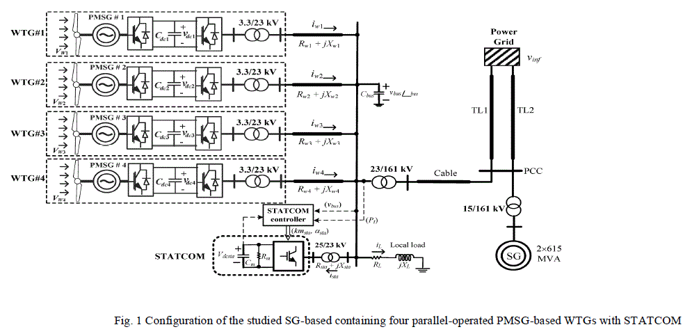
| Fig.1 shows the configuration of the studied system. The right-hand side of Fig.1 represents the synchronous generator (SG)-based one-machine infinite-bus (OMIB) system. Two parallel-operated 615-MVA SGs are connected to an infinite bus (or a power grid) through two parallel transmission lines (TL1 and TL2) and a 15/161-kV step-up transformer. Four parallel-operated PMSG-based WTGs and a 5-MVAR STATCOM are connected to the common offshore ac bus that is fed to the point of common coupling (PCC) of the OMIB system through a step-up transformer of 23/161 kV and a cable (undersea and underground cables). Each 5-MW WTG is represented by a PMSG with an ac/dc converter, a dc link, a dc/ac inverter, and a step-up transformer of 3.3/23 kV. While the shaft of the wind PMSG is directly driven by a variable-speed WT. the four PMSG-based WTGs, the STATCOM, and a local load are connected to a common ac bus through connection lines and transformers. |
 |
WIND TURBINE MODEL |
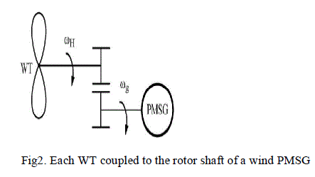
| The blade pitch angle (degrees) are the constant coefficients. The wind speed is modeled as the algebraic sum of a base wind speed, a gust wind speed, a ramp wind , and a noise wind speed. The cut-in, rated, and cut-out wind speeds of the studied WT are 4, 14, and 25 m/s, respectively. When wind speed is lower than 14 m/s, When 14 m/s, the pitch-angle control system activates and increases accordingly. In fig.2 Each WT is directly coupled to the rotor shaft of a wind PMSG. |
 |
PMSG AND POWER CONVERTER |
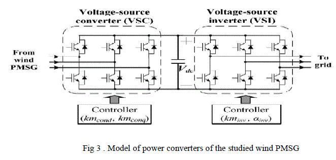
| The power converter of each wind PMSG consists of a voltage source converter (VSC) and a voltage-source inverter (VSI) as shown in Fig. 3. The VSC or the VSI consists of six insulated gate bipolar Properly decoupled by the dc- link capacitor . The common dc link with a large capacitor is connected between the VSC and the VSI. The operation of the VSC and the VSC is properly decoupled by the dc-link capacitor and, hence, the VSC and the VSI have independent controllers. |
 |
STATCOM MODEL |
| In order to temporarily avoid the high level of reactive compensation during recovery. In addition to the normal STATCOM control, allows for torque transient alleviation during the recovery process after a grid fault [4]. This is possible to achieve by reducing the voltage reference of the STATCOM control system and, by that, the reactive compensation when stability is ensured after fault clearing but before the grid voltage and the speed of the generator have returned to the prefault values [6]. In this way, the STATCOM can improve the torque capability of the PMSG when this is needed keep the system stable, and once stability is ensured, it can reduce the maximum torque during recovery. The strain on the drive train can thereby be reduced. This is particularly relevant where wind turbines cannot just disconnect from the grid to protect the installation from risk of mechanical damage that might be caused by the cumulative stress of repeated peak torque transients[5] This paper focuses on the recovery process after fault clearing and reactive power compensation .The other main issue related to this concept is that, since the decelerating torque of the generator is limited, the recovery process of the system will be longer than for the case of normal control of the STATCOM with a fixed voltage reference value[8]. |
SIMULATION RESULTS |
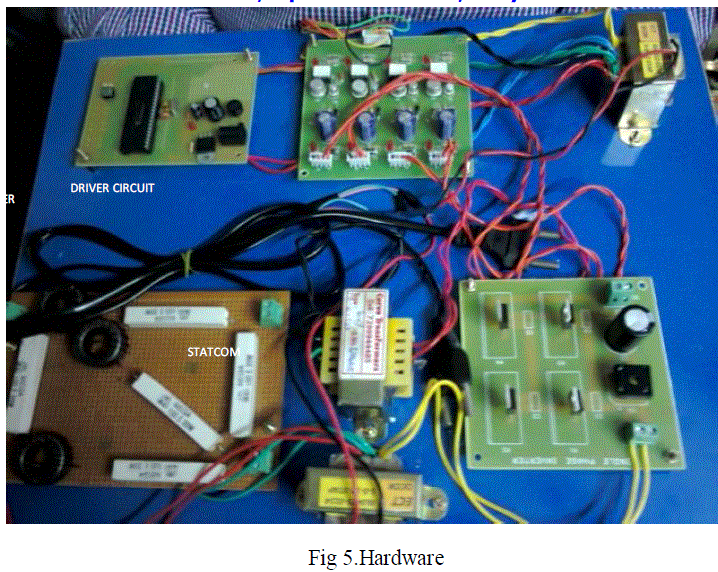
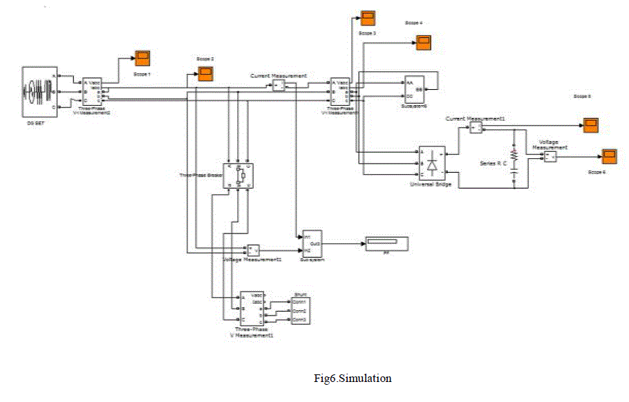
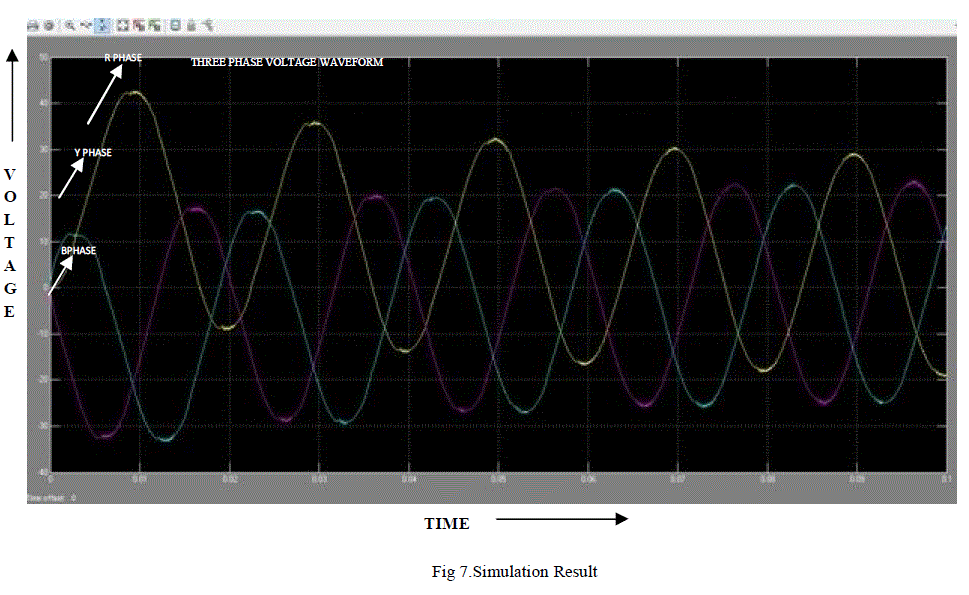
| It is noted that the reactive power exchange between the AC system and the compensator is controlled by varying the magnitude of the fundamental component of the inverter voltage above and below that of the AC system. The compensator control is achieved by small variations in the switching angle of the semiconductor devices , so that the fundamental component of the voltage produced by the inverter is forced to lag or lead the AC system voltage by a few degrees. This causes active power to flow into or out of the inverter modifying the value of the DC capacitor voltage and consequently the magnitude of the inverter terminal voltage and the resultant reactive power. If the compensator supplies only reactive power, the active power provided by the DC capacitor is zero. Therefore, the capacitor does not change its voltage. With the provision of DC source or energy storage device on its DC side, there can be a little active power exchange between the STATCOM and the electric power system. When the phase angle of the AC power leads the inverter phase angle, the STATCOM absorbs real power from the AC system, if the phase angle of the AC power system lags the inverter phase angle, the STATCOM supplies real power to AC system. Without STATCOM is the system they will be a voltage drop. So that when STATCOM is used it will compensate the reactive power either by absorbing or generating in FIG.6 and FIG.7.When voltage is less it whenever fault occurs it can compensate the voltage drop. |
 |
 |
 |
CONCLUSION |
| This paper has presented the stability improvement of four parallel-operated PMSG-based WTGs connected to an SGbased OMIB system. The STATCOM is proposed and is connected to the common ac bus of the four WTGs to supply adequate reactive power and offer proper damping. A PID damping controller has been designed for the STATCOM using modal control theory to assign the mechanical mode and the exciter mode of the studied SG on the desired locations on the complex plane. Root-loci plots under various operating conditions and time-domain transient simulations of the studied system subject to a three-phase short-circuit fault at the power grid have been systematically performed to demonstrate the effectiveness of the proposed STATCOM joined with the designed PID damping controller on suppressing inherent SG oscillations and improving system stability under different operating conditions. It can be concluded from the simulation and hardware Fig .7 results that the proposed. |
References |
|