ISSN ONLINE(2278-8875) PRINT (2320-3765)
ISSN ONLINE(2278-8875) PRINT (2320-3765)
J. Doondi kumar1, T. Mahalakshmi2, A. sarath3, K. Sandhya4 and M. Grace Priscilla5
|
| Related article at Pubmed, Scholar Google |
Visit for more related articles at International Journal of Advanced Research in Electrical, Electronics and Instrumentation Engineering
The EBG structures were used for surprising the surface wave propagations in the antenna as we know the EBG’S used to enhance parameters of monopole antenna in the earlier research. In this paper we analyse the effect of radiation on EBG cells as we know that the EBG cells will be better reflecting surfaces where we can overcome the problem of maintaining the minimum distance between antenna and reflector. The surface currents of antenna and surfaces currents of EBGS will add together to increase the antenna radiation filed. Here in this paper we mainly concentrate on the E,H and J filed distributions in EBG cells when they are exposed to antenna radiation this will gives the understanding of TE and TM modes in EBGS.
Keywords |
| Energy band Gap structure, surface wave suppression, TE mode, TM mode. |
INTRODUCTION |
| The new artificial magnetic conductors were invented for replacing the regular ground planes and reflecting surfaces. These surfaces are also called as Energy band gap structures and High impedance ground planes. These surfaces do not support the propagation of surface waves in antennas. The surfaces currents of antenna and EBGS will add together when they are tuned to same band it is called constructive property and the surfaces currents will cancel each other when they are out of phase called as destructive properties are helping in enhancing antenna radiation are absorbing antenna radiation which is explained in paper [1]. And also used for directing energy which is explained in [2]. Here in this paper we analyse how the TE and TM modes exist in EBG cells when subjected to radiation of a isotropic antenna. The E, H and J filed analysis of EBG cells along with its mesh analysis are presented in this paper. |
ANTENNA AND EBG DESIGN |
| For the isotropic antenna a monopole antenna of arm length 3.16EM is taken which is operating at 2GHZ frequency and it‘s diameter is 0.2cm the ground is of dimensions 10.05*10.05cm and the EBG have placed vertically with a base ground of 8.37*3.5cm in YZ directions. And the patch size for EBG is 3.5*3.5cm in YZ direction and the pin via is of 0.1cm radius and 0.5cm height. And the entire design is shown in figure [1]. |
 |
SIMULATION RESULTS |
| Aïôÿ Return loss:- |
| The return loss curves are taken by the S11 matrix verses frequency here these curves will explain how much loss of antenna can be reduced by suppressing the surface wave propagations and here antenna is working around 2.4GHz. These curves are shown in following figure [2]. |
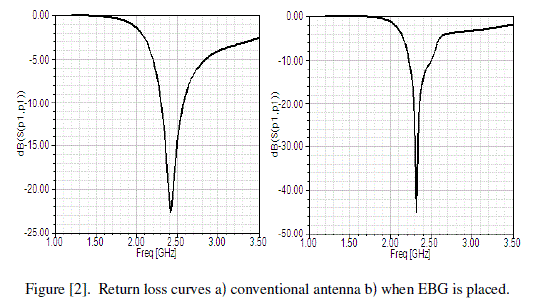 |
| By the above figure we can see that the operating frequency of antenna can slightly changes when we place EBGS. In fig [1] a, the return loss is -22.5075dB when EBG is placed it changes to -46.05dB shown in fig [1] b. |
| Bïôÿ Radiation pattern:- |
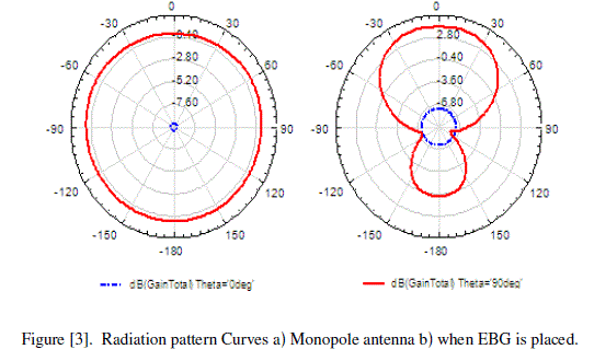
| The radiation pattern curves are shown in the following figure [3]. The radiation pattern curves are taken for phi=0º and phi=90º and the radiation pattern is Omni-directional for monopole antenna as shown in the figure [2] a. And figure [2] b shows the radiation pattern when EBG is placed at one end of the antenna we can see that the surface currents are added together to enhance radiation from around 0.40dB level to around 3dB level in the opposite direction of EBGS. |
 |
| CïôÿTotal gain in top view:- |
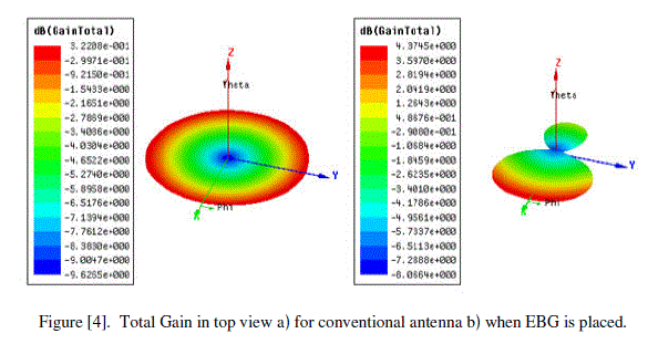
| The total gain curves are shown in the following figure [4] by the figure we can see that the maximum value of total gain is 3.2208dB for conventional antenna and 4.8676dB when EBGS is placed this shows how the EBG surfaces helps in enhancing the antenna parameters. Especially in enhancing radiation energy in opposite direction of EBGS. |
 |
| Dïôÿ E-filed in EBG cells:- |
| The E field in EBG cells is shown in the following figure [5]. |
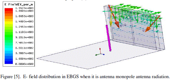 |
| Because of its high impedance, the surface wave modes on this EBGS are very different from those on a smooth metal sheet. It can support tightly bound, It can support TE modes that are bound to the surface at some frequencies, but radiate readily at other frequencies. In TE surface waves, the electric field is tangential to the surface of EBGS as shown in figure [6]. |
 |
| Eïôÿ H-field in EBG cells :- |
| The H field in EBG cells is shown in the following figure [7]. |
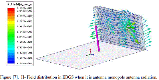 |
| TM surface wave propagating across EBGS is shown in Figure [8]. The magnetic field is transverse to the direction of propagation, associated with longitudinal currents flowing on the conductor. The electric field is linked to charge separation on the top of the conductor, and it jumps out of the surface in loops. The charges oscillate, and the wave propagates along the surface at nearly the speed of light. |
 |
| Fïôÿ J-field in EBG cells :- |
| The J field in EBG cells is shown in the following figure [9]. |
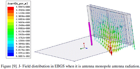 |
| This figure illustrates the surface currents in EBGS out of phase with 180º. |
| Gïôÿ Mesh analysis |
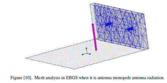
| The mesh analysis in EBG cells when they are in monopole antenna radiation is shown in the following figure [10]. |
 |
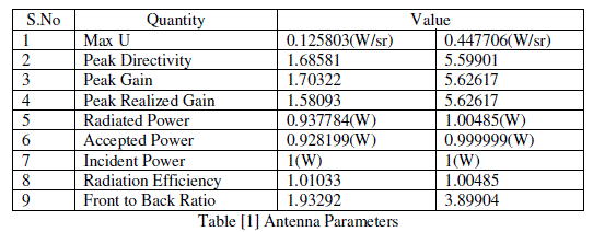 |
| The above table [1] illustrates the antenna parameters enhancement from conventional antenna to Antenna with EBGS at one end. |
CONCLUSION |
| When we place EBGS at one end of the antenna due to radiation of the antenna E and FH fields will induced in EBGS the H filed will be in loops around the EBG cells and E field is tangential to the EBG surface. And the surface currents are propagated in the direction of pane this explains the TE and Tm modes in EBGS and the working of EBGS in replacing the normal plane metal sheets. |
References |
|