ISSN ONLINE(2319-8753)PRINT(2347-6710)
ISSN ONLINE(2319-8753)PRINT(2347-6710)
|
Kunjan Sanadhya, N. P. Gokhale, B.S. Deshmukh, M.N. Kumar and D.B. Hulwan Kirloskar Oil Engines Ltd., Pune, India, [5]Vishwakarma Institute of Technology, Pune, India |
| Related article at Pubmed, Scholar Google |
Visit for more related articles at International Journal of Innovative Research in Science, Engineering and Technology
This project work involves experimental investigation of helical inlet port flow characteristics for cylinder head of Direct Injection (D.I) diesel engine. The average flow coefficient and swirl number is obtained using a paddle wheel test bench. Intake port helix parameters, i.e., distance between peripheral side wall and valve axis ‘Dp’, width of helical section parallel to valve axis ‘W’ and initial width of the helix ‘Wh’ are measured for different flow boxes for selected different bore and stroke engines. These parameters are modified and detailed analysis has been done to establish the effect on swirl number and average flow coefficient. The second part of work focused on the Computation Fluid Dynamics (CFD) to study flow velocity, flow distribution inside cylinder and to analyze effect of helix parameter change. The experimental study of combined effect of helix parameters, ‘W’, ‘Wh’ and ‘Dp’ indicates that this modification can be initiated for improving flow characteristics if change required in average flow coefficient is small as compared to higher amount of change required in swirl number. The CFD analysis with this modification also shows improvement in swirl generation and flow distribution.
Keywords |
| Average Flow Coefficient, Diesel Engine, Helical Port, Paddle wheel, Swirl Number |
INTRODUCTION |
| Air motion into the cylinder during intake stroke of an internal combustion engine is one of the important factors, which govern the performance of an engine. Swirl is the rotation of charge about cylinder axis and it is used in diesel engines to control air-fuel mixing. Several research studies related to swirl enhancement in IC engines reported that swirl facilitates mixing of air fuel mixture and increases the combustion rate. Furthermore, a high swirl is also not desired, as kinetic energy for the flow is obtained at expense of a reduced volumetric efficiency. Optimum swirl can be created by optimum design of the intake port. An optimal swirl ratio is not only good for optimum combustion, but also for an optimal emission reduction [2]. |
| Techniques like paddle wheel anemometer and torque meter are commonly used for steady state swirl measurement [5] and also laser doppler anemometry is used by many authors for study of in-cylinder bulk flow and turbulence structure [4]. The steady state flow analysis helps to find variations in different non-dimensional parameters such as flow coefficient and swirl ratio for various valve lifts. The test results available as comparative ratios, are very useful for obtaining very good approximation of actual engine conditions and for development work on helical inlet valve ports. This research work is carried out for helical intake ports of five DI diesel engines by using paddle wheel anemometer technique. |
| Various port modification techniques has been adopted by various authors to improve the flow characteristics of helical intake ports like throat machining [6] and changing parameters like valve cone angle [1], port position relative to cylinder [5], throat ceiling height [5], inlet centre distance [1], transition angle , helix slope angle and bottom slope [5]. |
| In this research work, effect of varying helical parameters i.e. distance between peripheral side wall and valve axis, width of helical section parallel to valve axis and initial width of the helix has been studied. These parameters are converted to non-dimensional form to compare the effect on all flow boxes. The effect of these parameters was studied for all the five experimental flow boxes and a trend is established which can be used to achieve required flow characteristics of any diesel engine helical port. |
| CFD as a tool can acquire a large amount of information which is unable to gain in experiments such as velocity field and flow field [3][4]. The simulation results can be analyzed in terms of distribution of in-cylinder swirl during intake process [5]. In this research work, velocity field and flow distribution was studied using CFD simulation software. At the end velocity field and flow distribution with and without modification were also compared. |
EXPERIMENTAL SETUP |
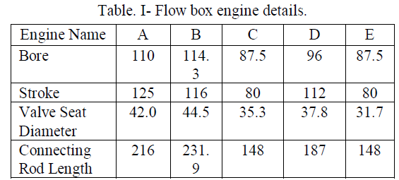
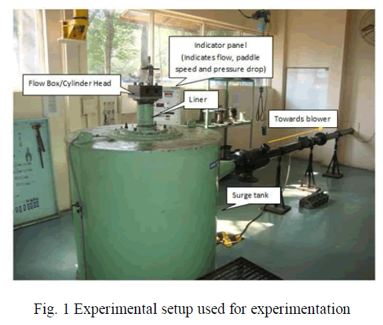
| A paddle wheel swirl test rig was used to determine swirl number and flow coefficient. The picture of the test rig is shown in fig. 1. The experimental work was carried out on helical intake port models, normally known as flow box. “A”, “B”, “C”, “D” and “E” is the nomenclature adopted for five flow boxes in this research work. The table. I show engine details of flow boxes used for test bench experimentation. |
| All flow boxes used for this experimental work were cylinder head models of engines with two valves per cylinder. For experimentation separate liners of bore sizes of table. 1 with mounting flanges was used and the test setup does not include piston. |
 |
| Valve assembly of the same engine type was mounted on the flow boxes and that flow box was placed on liner. Both liner and flow boxes were clamped using studs and nuts. Arrangement to change valve lift by measured amount using micrometer was also prepared. |
| A paddle wheel is normally mounted at a distance equal to 1.75 times bore diameter because the time taken for the charge to travel from the valve to 1.75 bore diameter position along the flow bench cylinder is equivalent to a time between maximum intake valve lift and top dead center firing in the running engine [6]. The paddle wheel diameters, length and height were taken as some ratio of bore and same ratio was used for all the trials. Also same vane thickness was used while preparation of paddle wheels. |
| Air is sucked by the blower through the port, over the valve, cylinder liner and surge tank as shown in fig. 1. This creates a vacuum below the valve. |
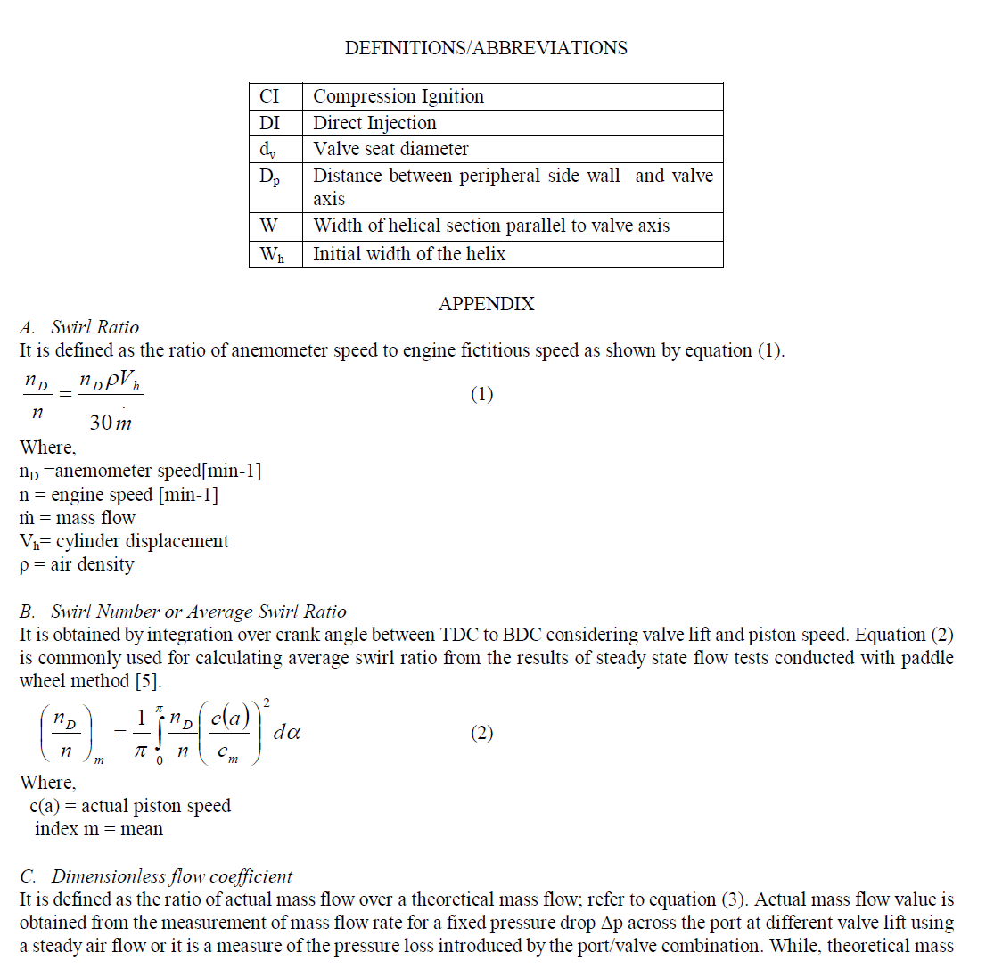
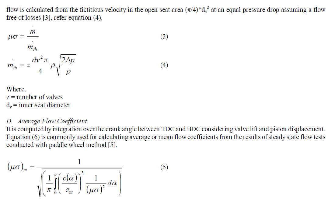
| The method used for experimentation is commonly used for calculating average or mean flow coefficients from the results of steady state flow tests conducted with paddle wheel method [5]. Typically the procedure used is based on the instantaneous measurement of mass flow rate, paddle wheel rotations per minute and pressure drop across the port at different valve lifts. Based on these measurements dimensionless flow coefficient and swirl ratio was computed at all valve lifts using equation (2) and equation (5). Since the swirl ratio measured in steady-state flow tests varies depending on valve lift, average swirl ratio during intake stroke can be defined as value found by integrating the angular momentum induced at each valve lift. The average flow coefficient during intake stroke can also be defined in the same way. Formulas used are included in Appendix. |
 |
METHODOLOGY |
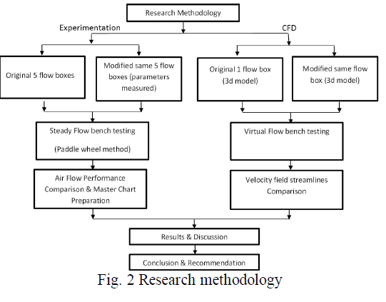 |
| Fig. 2 explains the methodology used for this research work. The experimental part of this research work has been focused on measuring swirl ratio and flow coefficient of five flow boxes at 13 valve lifts for original as well as modified flow boxes. After the test of original flow boxes, same flow boxes were modified and tested. Average flow coefficients and swirl number was measured from experimental outputs. The original and modified helix parameters were measured and normalized with valve diameter of engine to which the flow box belongs. The average flow coefficients and swirl number were compared for flow boxes before and after modifications using these normalized parameters. The CFD simulation was also carried out with intake port 3d model of one engine from experimental engines of table. I to see the effect of helix parameter change on velocity profiles and flow patterns by using mass flow rate from experimentation. |
GEOMETRY PARAMETER MODIFICATION |
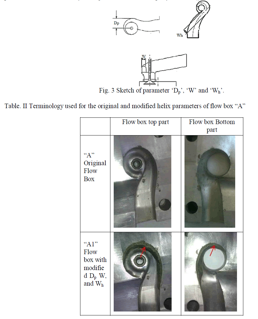
| Three helix parameters, specifically, distance between peripheral side wall and valve axis ‘Dp’, width of helical section parallel to valve axis ‘W’ and initial width of the helix ‘Wh’ shown in Fig. 3 have been modified on all flow boxes. These parameters were modified by adding material (known as putty) as shown in table. II. |
 |
| All these parameters are related to helix and hence were modified together to retain helix shape of the helical intake port. The modification done by this method can be undone unlike methods similar to polishing or material removal [2] from flow box. |
| In this paper, “A” is used as a representation for original flow box and “A1” is used for modified flow box representation as explained in table. II. Similar nomenclature is used for flow boxes “B”, “C”, “D” and “E”. |
GEOMETRY PARAMETER NORMALIZATION |
| The helix parameters ‘Dp’, ‘W’ and ‘Wh’ were measured for all flow boxes before and after modification. These parameters were then normalized with respect to valve seat diameter of that particular flow box or equivalent engine. Table. III and Table. IV lists the normalized helix parameters of tested original and modified flow boxes. |
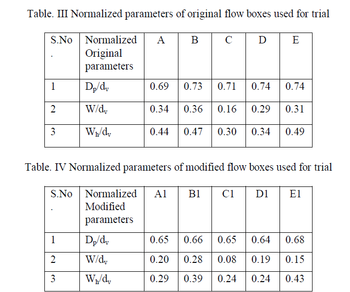 |
| This normalization technique allows eradication of engine size effects from data and can be used to compare measured dimension of flow box of different engines . In this research work, these normalized parameters were used to study the effect of helix modification on average flow coefficient and swirl number calculated using experimental results . |
COMPUTATIONAL FLUID DYNAMICS |
| A. Model details and boundary conditions |
| Three dimensional model including cylinder, valve and helical port was used for the study of velocity field and flow streamline in engine “D”. After importing model in software, it was split to separate the boundaries in outlet, cylinder, valve, port and inlet boundaries. Surface and volume meshing was done for the model with 13 mm valve lift. A steady flow case with incompressible working fluid was considered. As the experimental setup does not include piston, no piston was used for CFD model also and bottom of the cylinder was kept open and K-epsilon turbulence model was used. Constant mass flow rate at 13 mm valve lift obtained from experimental data was used as inlet boundary condition and static pressure of 0 Pa was used as boundary condition at outlet open end. |
| B. Model Validation |
| Using above boundary conditions, mass flow averaged pressure at inlet and outlet were obtained from the analysis. Equation (3) was used for flow coefficient measurement. Where, actual mass flow is taken as the mass flow used for inlet boundary condition which is same as the experimental mass flow result, while theoretical mass flow was measured using equation (4). Valve seat diameter was used same as that of engine “D”. |
| The flow coefficient obtained from above calculation was 0.51 while the flow coefficient obtained by experimentation for the same engine was 0.49. The flow coefficient result of CFD model and experimentation differs by 4 % which is acceptable. Thus, as the flow coefficient is similar to flow coefficient from experiment, the flow velocity field and flow streamlines plots inside the cylinder which are not obtained in the experiment can be studied using this method. |
RESULTS AND DISCUSSION |
| With the test bench data at different valve lifts swirl and flow coefficients was calculated for all flow boxes from equation (1) and equation (3) provided in the appendix and it was observed that increase in swirl ratio was significant at both higher and lower valve lifts while reduction in flow coefficient was less and observed only at higher valve lifts. Also, swirl number and average flow coefficient were calculated for all flow boxes and effect of changing the helix parameter on these flow characteristics was studied. These parameters were changed together as shown in table. II to maintain continuity of helical shape, but the effect of reduction of these normalized parameters was plotted individually for all parameters. Following section is divided in two parts. In first part the effect of helix parameter change on average flow characteristics is depicted while the second part depicts the effect of helix modification on velocity field and flow distribution using CFD. |
| A. Effect of helix parameter change on average flow characteristics |
| In modified flow box area reduction in the region of helix increase air velocity as compared to original flow box and air is forced to enter the cylinder liner with higher velocity and higher density. |
| Effect on Average flow coefficient |
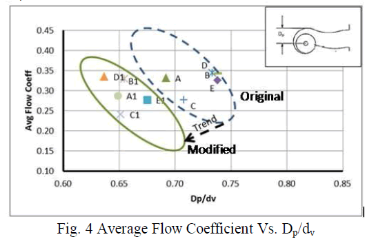
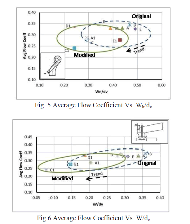
| As shown in fig. 4, fig. 5 and fig. 6 the calculated average flow coefficient is plotted against the normalized parameters from table III and IV. It was observed that all the flow boxes followed same trend where average flow coefficient reduced with reduction of parameters ‘Dp’, ‘Wh’ and ‘W’. |
 |
 |
| Effect on Average Swirl Ratio |
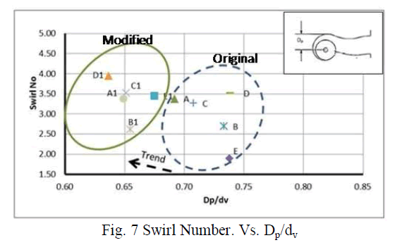
| Fig. 7, 8 and 9 shows that with ‘Dp’, ‘Wh’ and ‘W’ reduction, swirl number reduces. These parameters change the helical component of swirl. When helical component of swirl increases the swirl ratio of that port also increases at all valve lifts [1]. |
 |
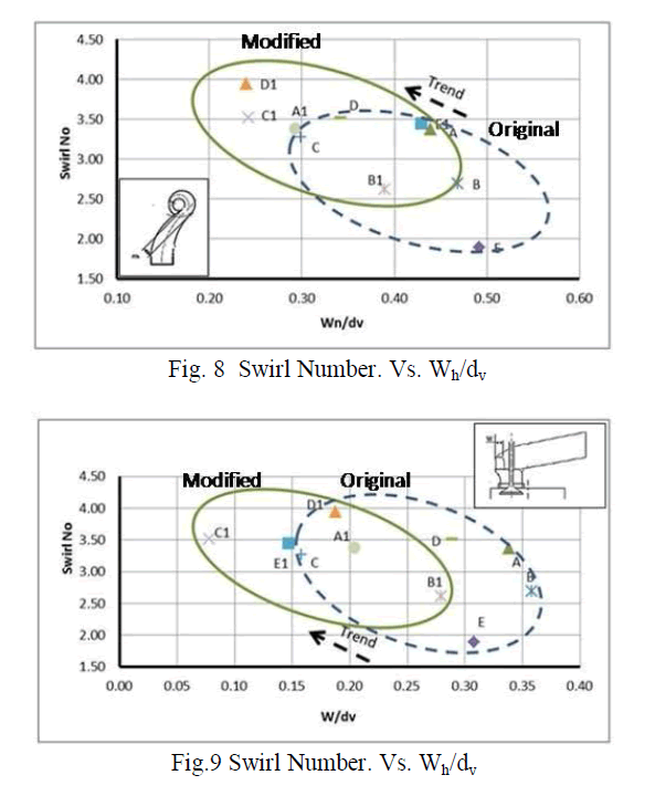 |
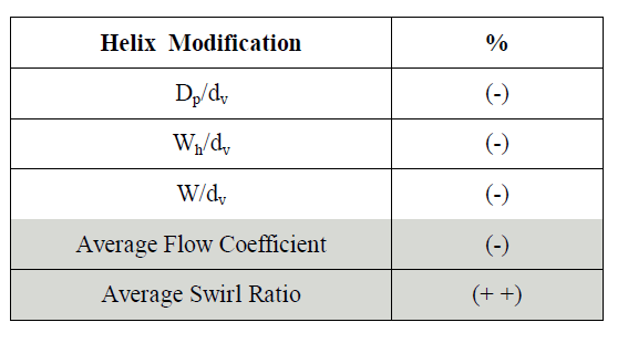
| The data from present study illustrates that average flow coefficient reduces by same percentage as that of change in parameter while the swirl number increases by double percentage. This outcome is listed in table V. As the average flow characteristics are derived from flow characteristics at each valve lift, little increase in average flow coefficient and significant increase in swirl number is observed because as per experimental data increase in swirl ratio was significant at both higher and lower valve lifts, while reduction in flow coefficient was observed only at higher valve lifts. |
| Table. V Change in average flow coefficient and average swirl number by helix parameters modification |
 |
| B. Effect of helix modification on velocity field and flow distribution by CFD |
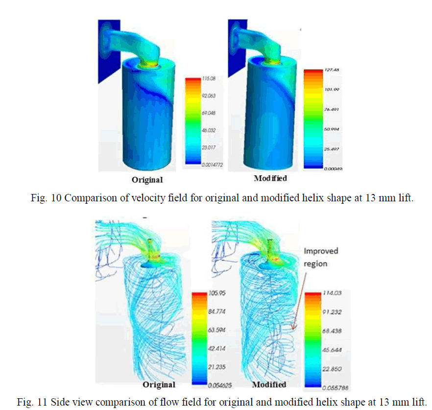
| The velocity field and flow distribution were studied using CFD simulation software. The CFD simulation results can be analyzed in terms of distribution of in-cylinder swirl during intake process [5]. As previously discussed the analysis was carried out for engine “D” and at 13 mm lift only. The fig.10 shows that flow velocity was increased after modification. Also swirl generation and swirl distribution around the cylinder was improved as shown in fig.11, fig.12 and fig.13. In fig.11 after modifications the velocity of streamlines just below the valve was reduced and the distribution inside the cylinder was improved as marked by arrow which shows that tangential velocity of air entering cylinder liner has increased and axial velocity has reduced. |
 |
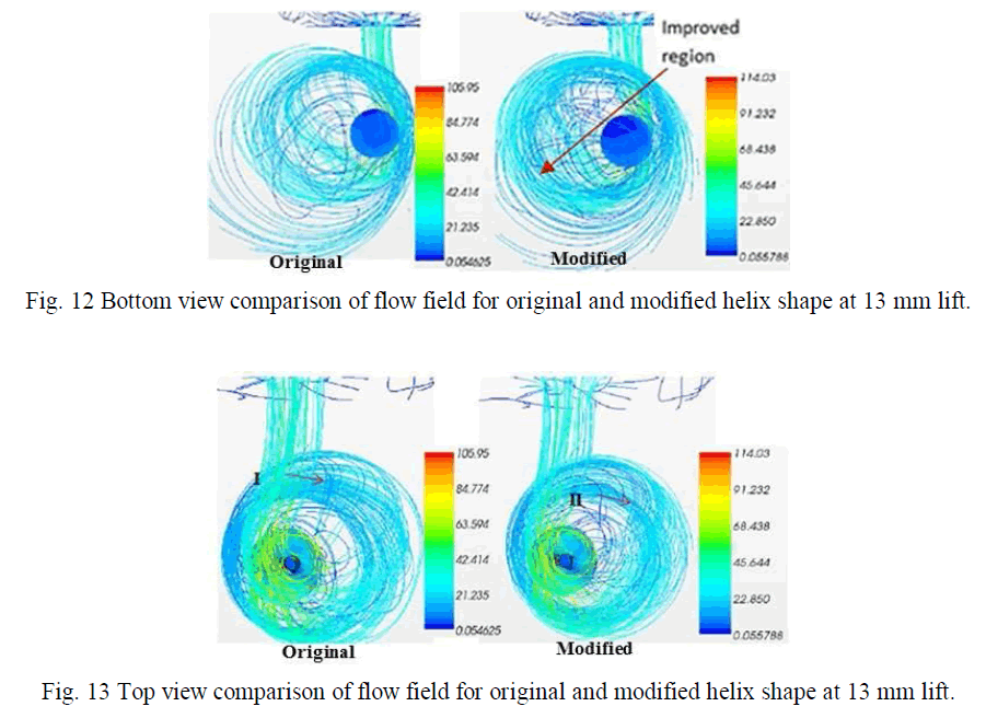 |
| The fig.13 explains that streamlines have shifted from position I to position II which means that more streamlines follows the cylinder wall and swirl is generated with better efficiency after modification. |
| Thus, as per CFD flow analysis, it is revealed that with helix parameter modification velocity increases and also the streamlines are enforced to follow the cylinder wall and the swirl is generated with better efficiency. |
CONCLUSION |
| As per this research work, helix modification is recommended to obtain the required flow characteristics, if change required in average swirl ratio is approximately double than opposite change required for average flow coefficient for a CIDI diesel engine cylinder head intake port. CFD analysis can be used to determine flow coefficient with approx 4 % variation from experimentation data. Both experimental and CFD analysis depicted that with helix parameter modification axial velocity component reduces and tangential velocity component increases resulting in better swirl generation. Also, CFD analysis has clarified that velocity near valve seat increases and the streamlines are enforced to move towards cylinder wall with helix modification which was difficult to explain from experimentation. |
ACKNOWLEDGEMENTS |
| With sense of gratitude and great pleasure, author would like to acknowledge the whole hearted co-operation extended by team of Corporate Research and Engineering, Kirloskar Oil Engines Ltd, Pune during entire research work. Author is also grateful to the management of Kirloskar Oil Engines Ltd. Pune for all support. |
References |
|
 |
 |