ISSN ONLINE(2319-8753)PRINT(2347-6710)
ISSN ONLINE(2319-8753)PRINT(2347-6710)
Mr. R. A. Patil1, Prof. V. D. Shinde2, Prof. H. V. Shete3, Prof. S. P. Nevagi4
|
| Related article at Pubmed, Scholar Google |
Visit for more related articles at International Journal of Innovative Research in Science, Engineering and Technology
Present study focuses on effect of high pressure coolant on surface finish of EN8 material during turning operation. In industry common practices is to use low pressure coolant up to 10 bar. In the present experimentation, instead of low pressure, high pressure coolant of 10 bar to 70 bar is used. The experimentation is done on CNC machine during turning operation of a particular job of EN8 material. It is concluded that increase of pressure results improved surface finish to considerable level.
Keywords |
| High Pressure coolant; Surface Finish; Roughness Average; Average Maximum Height of the Profile. |
INTRODUCTION |
| In the process of machining, a tool penetrates into the workpiece and removes the material in the form of chips. A major portion of the energy is consumed in the formation and removal of chips. The greater the energy consumption, the greater are the temperature and frictional forces at the tool–chip interface and consequently the higher is the tool wear. Flood or conventional coolant is applied to remove the heat generated at the cutting zone. During machining especially of very hard materials, much heat is generated by the friction of the cutter against the workpiece, which is one of the major causes of reduction in tool hardness and rapid tool wear [9]. However, high pressure jet of soluble oil, if applied at the chip-tool interface, the wedge formation by the jet may lift up the chip, segregating it and could break the vapor barrier and reduce cutting temperature and improve tool life The combination of reduced heat and more efficient evacuation of chips prolong tool life and makes replacement more predictable because the cutting tool wears out naturally rather than failing prematurely because of excessive heat or chip damage [1]. Application of pressurized coolant jet for effective cooling without polluting the environment is becoming more popular day by day. But in addition to pollution control, the industries also reasonably insist economic viability through technological benefits in terms of product quality, tool life and saving power consumption by the application of pressurized jet cooling. So it has become essential to study the role of high- pressure cooling on cutting temperature, chips, cutting force, tool wear, tool life and surface quality of the product in machining where high cutting temperature is the major concern. Therefore, there have been several studies on applying coolant at high pressure at the tool–chip interface, focused on a stationary single cutting edge in a turning operation. The performance of high-pressure coolant is investigated by focusing on cutting forces, surface finish, tool wear, and chip shape, which are compared against dry cut and conventional coolant. Cooling is important in reducing the severity of the contact processes at the cutting toolwork piece interfaces [8]. |
II. BENEFITS OF HIGH PRESSURE COOLANT |
| High pressure coolant can provide the following benefits especially in challenging work piece materials [3,7]. |
| a) Higher machining security |
| b) Consistent machining process. |
| c) Fewer machine stoppages |
| d) Better component quality, e) Improved surface finish f) Better chip control Shorter machining times g) Faster cycle time h) Better utilization of machine capabilities i) Multiplied tool life j) These benefits can also be applied milling and drilling concepts |
| The principle behind the application of high pressure coolant is that a reduction in the fluid outlet (nozzle on tool holder) produces an increase in the fluid velocity coming out of the nozzle. Larger the nozzle the higher the flow rate of the fluid. Moreover, the number of nozzles (accumulated outlet area) will affect the resulting fluid outlet pressure. Thus, there is a proven theory (Bernoulli’s) that expresses the relationship between pressure, velocity and flow rate of a fluid, such as a coolant. As the fluid passes from a larger-diameter tube to a tube that is smaller in diameter, the flow rate requirements are smaller to achieve a high-velocity jet – the effect of putting a nozzle on the end of a garden hose. The larger the nozzle outlet diameter, the greater the flow rate requirement needed to deliver a certain pressure [1] |
III. HIGH PRESSURE COOLANT |
| The application of coolants in machining is undergoing somewhat of a re-evaluation. Many machine shops have used coolant in a conventional way, directing a tube which floods the machining zone. Today, some machine shops question the use of coolant altogether and introduce dry turning. Some use it only to control dust, chip evacuation or for finishing to achieve required surface quality and tolerance. Just flooding the machining zone with coolant is not enough. If coolants are to be applied effectively they need to be applied through high pressure jets that are directed correctly. Such a jet, when controlled in a laminar flow, shortens the contact length between chip and rake face. In this form, coolants can affect how the generated heat is distributed and removed, the amount of tool wear generated, how chips are formed and broken as well as the amount of smearing of work piece material on the cutting edge. This becomes especially important when machining demanding materials, where heat and chip control need extra measures [3]. Today, two main basic conditions are in place to improve machining with high pressure coolant: Many CNC machines have coolant supplies at pressures of at least 70 bar (1015 psi) as standard or optional and many have a tool holding system that is suited for high pressure coolant supply. The challenge thus is to make better use of the available machine tool capability, using the best tooling system. The aim is to achieve the best balance of running time the right continuous machining rate rather than excessive rates with numerous stoppages or rates that are unnecessarily low. Even handling tools equipped with high pressure coolant is as easy and efficient as ordinary tools, with no operator settings of coolant jets. The benefits apply to both external and internal operations as well as grooving, profiling and pocketing [3, 5, 8]. In turning, the nozzle size recommended to produce a High Pressure (HP) precision coolant jet with laminar flow is 0.039 inch (1 mm) in diameter. A flow rate of at least 5.3 gallons (20 liters) per minute is recommended. Exchangeable nozzles with outlet holes are available between 0.24 to 0.55 inch (0.6 to 1.4mm) The coolant pressure recommended for optimum Turn HP turning, as well as for Mill milling and Drill drilling, for high performance and results in most work piece materials is 80 bar (1160 psi). For each 0 .039 inch (1 mm) nozzle being employed in the tool, a coolant flow-rate of 1.3 gallons (5 liters) per minute is required to maintain pressure. The variation in nozzle-outlet size should be used to maximize the pressure and utilize the available flow rate [3]. |
IV. SURFACE ROUGHNESS GEOMETRY |
| No surface is perfectly smooth, but the better the surface quality, the longer a product generally lasts, and the better it performs. Surface roughness is an important measure of product quality, since it greatly influences the performance of mechanical parts as well as production cost. Surface roughness has an impact on the mechanical properties like fatigue behavior, corrosion resistance, creep life, etc. It also affects other functional attributes of parts like friction, wear, light reflection, heat transmission, lubrication, etc. Surface finish, by definition, is the allowable deviation from a perfectly flat surface that is made by some manufacturing processes. Whenever any process is used to manufacture apart, there will be some roughness on the surface. This roughness can be caused by a cutting tool making tiny grooves on the surface or by the individual grains of the grinding wheel each cutting its own groove on the surface. It is affected by the choice of tool, speed of the tool, environmental conditions, and definitely by what material are working with. Even when there is no machining involved, as in casting, molding, the surface of the mold will have surface deviation, which in turn will be transferred onto the part. Even if it could create a mold which was perfectly flat, the cooling process and thermal properties of the material would cause surface imperfections. [10] |
V. ROUGHNESS AVERAGE (Ra) |
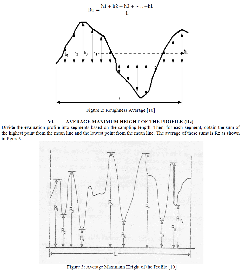
| Ra is the universally recognized parameter of roughness. It is the arithmetical mean of the departures of the profile from the mean line. Statistically Ra is a very stable, repeatable parameter as shown in figure 2. The average roughness is by far the most commonly used parameter in surface finish measurement. The earliest analog roughness measuring instruments measured only Ra by drawing a stylus continuously back and forth over a surface and integrating (finding the average) electronically. It is fairly easy to take the absolute value of a signal and to integrate a signal using only analog electronics. Ra is used in the automotive and other metalworking industries to specify surface finish of many types of components ranging from cylinder bores to brake drums [10] |
 |
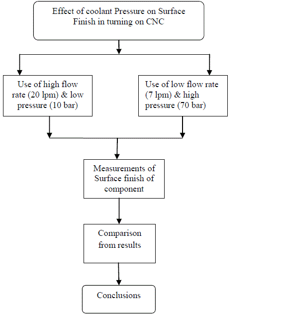
VII. METHODOLOGY |
 |
VIII. EXPERIMENTATION |
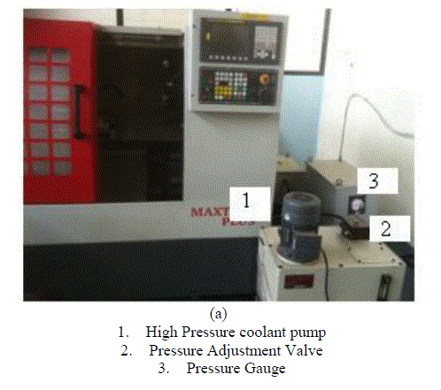
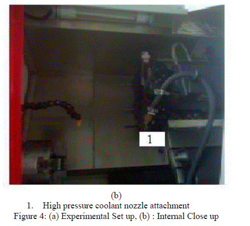
| The experiments are performed on Maxturn plus CNC Machine with high pressure pump set attachment. The set up is shown in figure 4. The high Pressure coolant attachment is prepared to supply high pressure coolant during turning operation. The fixed parameters in the experimentation are as follows Work material – EN8 Steel Machining method – Turning Tool – Single point cutting tool Tool insert – DNMG (IC320), WNMG (IC9015) Cutting Conditions (speed, feed, depth of cut) Speed – 2000 rpm Feed – 0.1 mm/rev. Depth of cut – 0.2 mm Coolant – Water base Ashoka LD-700 The variable parameters of experiment are as follows Flow rate of coolant Pressure of coolant |
 |
 |
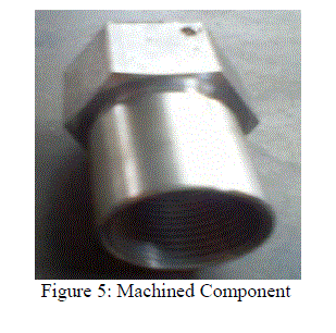
| The component for study is threaded nipple shown in figure 5. This is used for supplying the oil to the engine. On this component various machining operations are performed. For present study the turning operation on hexagonal bar of 25mm size is selected. |
 |
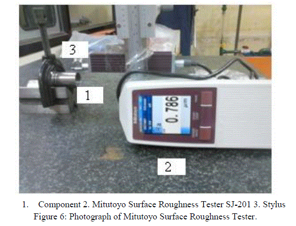
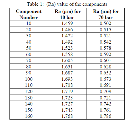
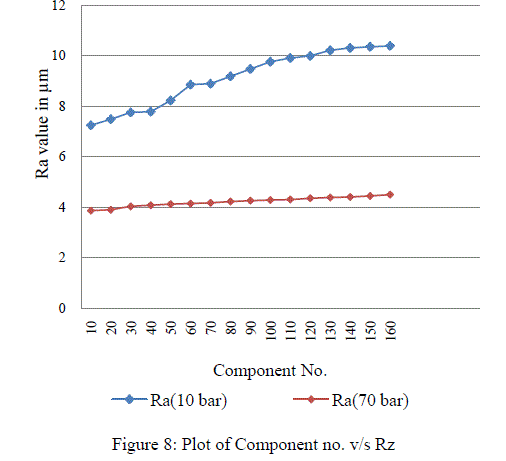
| The Surface finish of machined component is measured by Mitutoyo Surface Roughness Tester SJ-201 as shown in figure 6and Table 1 shows Roughness Average (Ra) value of components. Table 2 shows Rz value of components. The readings are taken for every 10th component machined at pressure 10 bar & pressure 70 bar and compare the component up to 160 component were the tool is change at 10 bar pressure. |
 |
 |
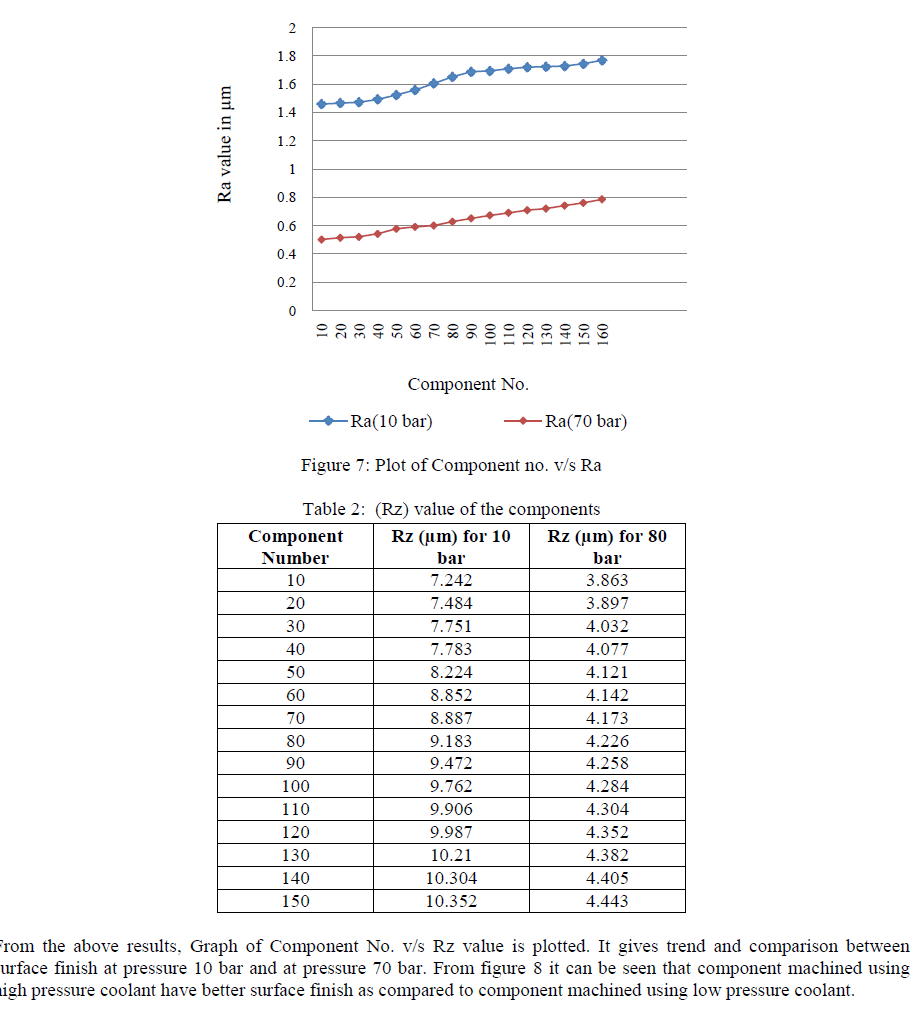
| From the above results, Graph of Component No. v/s Ra value is plotted. It gives trend and comparison between surface finish at pressure 10 bar and at pressure 70 bar. From figure 7 it can be seen that component machined using high pressure coolant have better surface finish as compared to component machined using low pressure coolant. |
 |
 |
IX. CONCLUSIONS |
| a. Use of high pressure coolant improves the surface finish considerably. |
| b. At low pressure (10 bar) the minimum surface roughness value is 0.978 μm and maximum surface roughness value is 1.687 μm. At high pressure (70 bar) the minimum surface roughness value is 0.542μm and maximum surface roughness value is 0.817μm. |
| c. Surface roughness shows increasing trend for both low pressure (10 bar) as well as high pressure (70 bar) coolant supply. This is due to tool wear. |
| d. Surface finish of 200th component (0.817μm) machined using high pressure coolant (70 bar) is less compare to the 1st component (0.978 μm) machined using low pressure coolant (10 bar). |
| e. At low pressure (10 bar) the minimum average maximum height of the profile value is 7.242 μm and average maximum height of the profile value is 10.352 μm. At high pressure (70 bar) the minimum average maximum height of the profile value is 3.863μm and maximum minimum average maximum height of the profile value is 4.443. |
References |
|