Keywords
|
| Microstrip Antenna, Unipolar, Slot, Ominidirectional. |
INTRODUCTION
|
| Microstrip antennas (MSAs) are more popular because of their compact size, simple in design, low cost and capable of operating more than one band of frequencies. Owing to their thin profile, light weight, planar configuration, broader impedance bandwidth, unipolar configuration and easy fabrication, the MSAs are the better choice for these requirements. Numbers of investigations have been reported in the literature for the realization dual-band using stacked shorted patch antenna [3], circular polarization for dual band operation [4], slot loaded patch [5], use of pair of arcshaped slots for dual band operation [6], triangular microstrip antenna with a pair of narrow slots [7], rectangular microstip patch antenna with pairs of spur-lines [8], compact triple band antenna for WLAN, WiMAX applications [9], multiband microstrip antenna [10] etc. In this paper a simple technique has been demonstrated to construct the unipolar rectangular microstrip antenna for quad-band operation with ominidirectional radiation pattern by loading four square slots on the radiating patch. |
DESIGN OF ANTENNA GEOMETRY
|
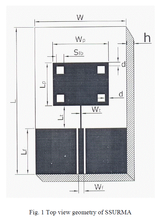
| The art work of the proposed antenna is sketched by using computer software Auto-CAD to achieve better accuracy and is fabricated on low cost FR4-epoxy substrate material of thickness of h = 0.16 cm and permittivity ïÃÂÃÂ¥r = 4.4. Figure 1 shows the top view geometry of square slots loaded rectangular unipolar microstrip antenna (SSURMA). In Fig.1 the area of the substrate is L * W cm. On the top surface of the substrate a ground plane of height which is equal to the length of microstripline feed Lf is used on either sides of the microstripline with a gap of 0.1 cm. On the bottom of the substrate a continuous ground copper layer of height Lf is used below the microstripline. The antenna is designed for 3 GHz of frequency using the equations available for the design of conventional rectangular microstrip antenna in the literature [2]. The length and width of the rectangular patch are Lp and Wp respectively. The feed arrangement consists of quarter wave transformer of length Lt and width Wt which is connected as a matching network between the patch and the microstripline feed of length Lf and width Wf. A semi miniature-A (SMA) connector is used at the tip of the microstripline feed for feeding the microwave power. In Fig.1 four square slots of equal dimensions are loaded on the radiating patch at distance of 0.2 cm from its horizontal and vertical sides. The length and width of slots is Slb. The design parameters of the proposed antenna is gives in Table 1 |
 |
 |
EXPERIMENTAL RESULTS AND DISSCUSION
|
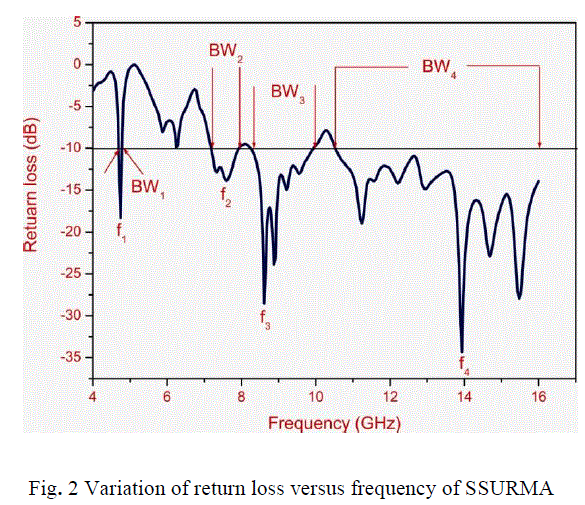
| The antenna bandwidth over return loss less than -10 dB is tested experimentally on Vector Network Analyzer (Rohde & Schwarz, Germany make ZVK model 1127.8651). The variation of return loss verses frequency of SSURMA is as shown in Fig. 2. From this graph the experimental bandwidth (BW) is calculated using the equations, |
 (1) (1) |
| were, f1 and f2 are the lower and upper cut of frequencies of the band respectively when its return loss reaches – 10 dB and fc is the centre frequency of the operating band. From this figure, it is found that, the antenna operates between 4 to 16 GHz and gives four resonant modes at f1 to f4, and three notch bands between 4.80 to 7.18, 7.91 to 8.25 and 9.97 to 10.47 GHz. The magnitude of experimental -10 dB bandwidth measured for BW1 to BW4 by using the equation (1) is found to be 140 MHz (2.95 %), 730 MHz (9.67 %), 1.72 GHz (18.88 %) and 5.53 GHz (41.78 %) respectively. From Fig.2 it is clear that, the antenna not only operates for quad bands but it also capable of rejecting the interference of HIPERLAN/2 (4.80 to 7.18) frequency range between BW1and BW2. |
| The resonant mode at 4.78 GHz is due to the fundamental resonant frequency of the patch and others modes are due to the novel geometry of SSURMA. The multi mode response obtained is due to different surface currents on the patch. The fundamental resonant frequency mode shifts from 3 GHz designed frequency to 4.78 GHz due to the coupling effect of microstripline feed and top ground plane of SSURMA. |
 |
| The gain of the SSURMA is measured by absolute gain method [10]. The peak gain of SSURMA measured in its operating bands is found to be 11.96 dB. |
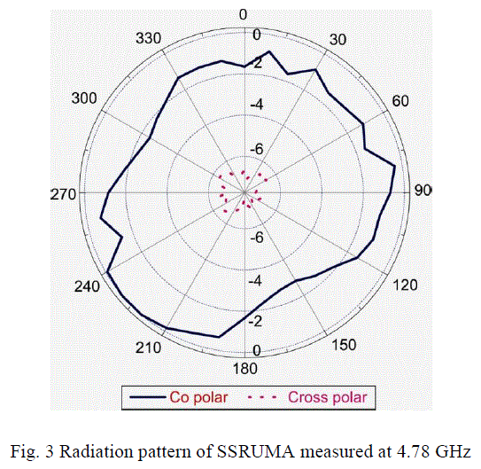
| The co-polar and cross-polar radiation pattern of SSURMA is measured at 9 .02 GHz and is as shown in Fig 3. The obtained pattern is ominidirectional in nature. |
 |
CONCLUSION
|
| From the detailed experimental study, it is concluded that, the SSRUMA with microstripline feed is capable of producing quad-band operation and gives peak gain of 11.96 dB. The antenna also capable of rejecting the interference of HIPERLAN/2 frequency range between BW1 and BW2 (i.e. 4.80 to 7.18 GHz). The antenna has simple structure and use low cost substrate material FR4. The proposed antenna operates in the frequencies range of 4 to 16 GHz and gives ominidirectional radiation characteristics. This antenna may find application in microwave communication systems. |
ACKNOWLEDGEMENTS
|
| The authors would like to thank Dept. of Sc. & Tech. (DST), Govt. of India. New Delhi, for sanctioning Vector Network Analyzer to this Department under FIST project. The authors also would like to thank the authorities of Aeronautical Development Establishment (ADE), DRDO, Bangalore for providing their laboratory facility to make antenna measurements on Vector Network Analyzer. |
References
|
- Constantine A. Balanis, Antenna theory analysis and design, John Wiley, New York, 1997.
- I. J. Bahl and P. Bharatia, Microstrip antennas, Dedham, MA: Artech House, New Delhi, 1981.
- H. K. Kan. Waterhouse. A. Y. J. Lee and Pavlickovski, “Dual frequency stacked shorted patch antenna.”Electron lett. vol..41, no.11, pp. 624-626, 2005.
- C.-H. Cai, J. –S Row and K. –L. Wong). “Dual frequency dual circular microstip antenna with polarization.”Electron lett. vol. 42, no. 22, pp. 1261-1262, 2006.
- S. Maci, G. BiffiGentili P. Piazzesi and C. Salvador, “Dual-band slot loaded patch antenna,” IEEE Proceedings on Microwave Antennas Propagation, no.142, pp.225-232. 1995.
- K. L Wong and K. B. Hsieh,“Dual frequency circular microstrip antenna with a pair of arc-shaped slots,” Microwave Optical Technology Letters, vol.19, pp. 410-412, 1998.
- S. T. Fang and K. L. Wong, “A dual frequency equilateral – Triangular microstrip antenna with a pair of narrow slots,” Microwave Optical Technology Letters, vol. 23, pp. 82-84, 1999.
- S.Hong and K.Chang, ”Single-feed triple- frequency rectangular microstip patch antenna with pairs of spur-lines,”Electronlett.vol. 42, no.12, pp. 673-674, 2006.
- K. G. Thomas and M. Sreenivasan, ,”Compact triple band antenna for WLAN, WiMAX applications,” Electron lett.vol. 45, no.16, pp.811- 813. 2009.
- M.Veereshappa and Dr.S.N.Mulgi, “Design and development of multi-band microstrip antenna with Ominidirectional Radiation Characteristics” International Journal of Electronics Engineering, 3 (2), pp. 313– 315, 2011.
|