In all-optical communication system, the signal remains in optical domain between the transmitter and receiver. As the optical signal propagates from the transmitter towards receiver, due to physical layer impairments of the network, its quality degrades. The factors affecting the physical layer of the optical network are the linear and nonlinear effects of fiber. In this paper analysis the linear and non-linear effects present in optical communication system. The performance of the optical communication system due to collective effect of FWM and SRS and due to combined effect of FWM and XPM has been discussed. Limitations of amplifier and its optimal location have also been discussed. In this paper the performance evaluation based on Q-factor vs transmitted power for FWM-XPM, SRSFWM, SRS-XPM and SRS-XPM-FWM-ASE nonlinearity in optical communication for 8 channels and 16 channels communication system.
Keywords |
| Stimulated Raman scattering (SRS), Amplified spontaneous emission noise (ASE), Cross phase
modulation (XPM), Self phase modulation (SPM), Four wave Mixing (FWM). |
INTRODUCTION |
| The need for large bandwidth in the transport network fabric has led to the acceptance of optical network as the
technology of choice for the core transport function. Optical fiber, as a medium in optical network, provides over 40
THz of available bandwidth that can be efficiently utilized using wavelength division multiplexing (WDM) [1, 2]. In
WDM, the entire optical bandwidth is divided into a number of channels centred at different wavelengths [3]. The
WDM network operates as an optical transport network carrying the traffic from existing network technologies (e.g.,
SONET/SDH, ATM, IP) and transporting them using light paths. Thus the WDM infrastructure consists of access
networks connected through WDM rings with the help of optical cross-connects (OXC) to the WDM mesh network [4,
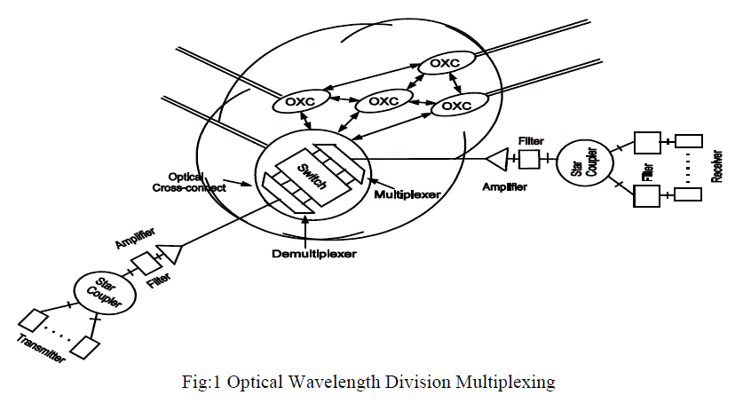
5]. A typical configuration of all optical wavelength division multiplexing network is shown in Fig. 1. The impact of
non-linear impairments on quality of transmission (QoT) is strongly dependent on the accumulated power and on the
individual power of the other optical channels transported in parallel on the same fiber whereas the impact of linear
impairments is independent of the power of each of the optical channels transported on the same fiber. In case of linear
impairments, QoT can be evaluated individually for the different optical channels sharing the same fiber. |
| When nonlinear impairments are considered, QoT of each optical channel transported on the fiber depends on the
number and the power of other channels transported simultaneously on the same fiber. The non-linear impairments are
self-phase modulation (SPM), cross phase modulation (XPM), four wave mixing (FWM), stimulated Brillouin
scattering (SBS) and stimulated Raman scattering (SRS) while the linear impairments are amplified spontaneous
emission (ASE) noise generated by EDFAs, polarization mode dispersion (PMD), chromatic dispersion (CD) of fiber
and OXC crosstalk. Due to non-linear and linear impairments, quality of the signal at some intermediate node may
degrade beyond recognition. In such cases, regenerators have to be placed at intermediate nodes. |
| The paper is organized as follows. In sections II, non-linear impairments of optical network are discussed. . In sections
III, linear impairments of optical network are discussed. In section IV, simulation results for the performance
evaluation based on Q-factor vs transmitted power for FWM-XPM, SRS-FWM, SRS-XPM and SRS-XPM-FWM-ASE
nonlinearity in optical communication for 8 channels and 16 channels communication system are discussed. We
conclude the article in Section V and discuss several outstanding research issues. |
 |
NON-LINEAR IMPAIRMENTS |
| These impairments are due to non-linear effects in the optical fiber and can arise either due to change in the refractive
index of the medium with optical intensity (power) or due to inelastic-scattering phenomenon. The non-linear effects
are briefly explained below. |
A. SELF PHASE MODULATION (SPM) |
| SPM occurs due to the non-linear phase modulation of an optical pulse caused by its own intensity in an optical
medium. As an optical pulse travels down the fiber, the leading edge of the pulse causes the refractive index of the fiber
to increase causing a blue shift while the falling edge of the pulse decreases the refractive index causing a red shift.
These shifts introduce a frequency chirp on each edge and the signal is broadened in the frequency domain by an
amount given as |
 |
| where dp/dt is the time derivative of the pulse power, γ is the non-linear coefficient and L eff is the effective length. The
primary effect of SPM is to broaden the pulse in the frequency domain, keeping the temporal shape unaltered, while
dispersion causes broadening of the pulse in time domain keeping the spectral contents unaltered. Hence, broadening of
the pulse occurs only when the shifts introduced by the frequency chirp interact with fiber dispersion. The effects
produced by SPM and dispersion are opposite in nature and by choosing proper pulse shape and input power, one effect
will compensate for another, leading to undistorted pulse in both time and frequency domains. SPM is the strongest
among the Kerr effects for DWDM systems working at 100 GHz spacing and the chirp depends on the input pulse
shape. |
CROSS PHASE MODULATION (XPM) |
| XPM originates from the intensity dependence of the refractive index, which results in intensity dependent phase-shift
as signal propagates through the fiber. When there is more than one optical signal propagating through the fiber as in
multichannel WDM, the non-linear phase shift of a signal not only depends upon its own power but also on the power
of other signals [23]. For example, if there are four signals, the non-linear phase shift of the first signal [22] is given by where Pi i =1 to 4 are the powers of the four signals and Leff the effective length of the fiber. The first term in above
equation is due to SPM while other terms are due to XPM that represents the phase-modulation (PM) process. In presence of group velocity dispersion (GVD), this PM is converted into IM (intensity modulation), which degrades the
quality of the signal. The XPM-induced phase shift can occur only when two pulses overlap in time due to which the
intensity-dependent phase shift and consequent chirping is enhanced, leading to asymmetric spectral broadening and
distortion of the pulse shape. |
 |
| where Pi i =1 to 4 are the powers of the four signals and Leff the effective length of the fiber. The first term in above
equation is due to SPM while other terms are due to XPM that represents the phase-modulation (PM) process. In presence of group velocity dispersion (GVD), this PM is converted into IM (intensity modulation), which degrades the
quality of the signal. The XPM-induced phase shift can occur only when two pulses overlap in time due to which the
intensity-dependent phase shift and consequent chirping is enhanced, leading to asymmetric spectral broadening and
distortion of the pulse shape. |
FOUR WAVE MIXING (FWM) |
| In a WDM system, due to the non-linear nature of the refractive index, when signals of frequencies fi, fj, fk propagate in the fiber, non-linear interaction will generate new components [23] at frequencies (fi ± fj ± fk) . Thus, |
 |
| For example, if i=1, j=2 and k=3, FWM components that are generated (excluding the case i=k and j=k) are f
321f
231
, f
312
, f
213
, f
332
, f
331
, f
223
, f
221
, f
113
and f
112
. Some of these generated FWM components lie on the transmitted carrier causing
interference [24]. The generated signal power is expressed as |
 |
 |
 |
| The total FWM power generated at frequency f
x
is given by [37] |
 |
| The crosstalk due to FWM is the dominant non-linear effect in long-haul DSF based WDM systems. If the channels are
equally spaced (known as equally spaced channel allocation scheme (ESCA)) the number of FWM components
generated grows rapidly as the number of channels is increased. |
STIMULATED RAMAN SCATTERING (SRS) |
| SRS is due to interaction of incident light wave with vibrational modes of silica molecule i.e., if two or more optical
signals at different wavelengths are injected into a fiber, SRS causes energy from lower wavelength channels to be
transferred to the higher wavelength channels. This in turn reduces the signal-to-noise ratio of the lower wavelength
channels and introduces crosstalk on higher wavelength channels which can lower the information carrying capacity of
the system. The threshold power in case of SRS can be estimated as [22] |
 |
| where gR is the Raman gain and Leff the effective length of the fiber. If the fiber is sufficiently long, then Leff ≈ 1/α. In
that case |
 |
| The value of gR is 1 x 10-13 m/W for silica at λ =1550 nm. The value of α as 0.2 dB/km and Aeff as 55 2 μm, results in Pth
equal to 570 mW. Hence, the effect of SRS is insignificant in case of single channel. |
LINEAR IMPAIRMENTS |
A. CHROMATIC DISPERSION (CD) |
| A light source generates signal with closely spaced wavelengths. As the refractive index of fiber is a function of
wavelengths, these wavelengths travel through the fiber at different speed. It gives rise to pulse broadening at the
receiver which results in inter symbol interference (ISI). CD is a measure of change of refractive index with wavelength
and is expressed as ps/nm.km. |
B. AMPLIFIED SPONTANEOUS EMISSION (ASE) NOISE |
| Optical amplifiers play an important role in the design of long haul optical communication networks. EDFA is the
commonly used optical amplifier in a long-haul WDM network. It has the capability of amplifying multiple
wavelengths simultaneously. The amplifier can either be placed at position ‘a’ (as booster amplifier), or at position ‘b’
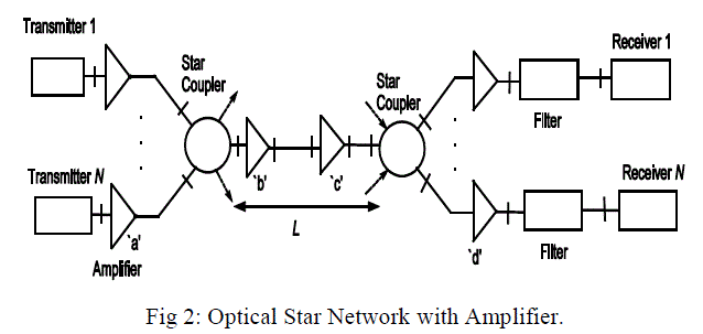
and ‘c’ (as in-line amplifier), or at position‘d’ (as pre-amplifier) as shown in Fig. 3. |
 |
| Amplifier produces amplified spontaneous emission (ASE) noise. The average total power of amplified spontaneous
emission (PASE) is given by |
 |
| where hv is the photon energy, G the amplifier gain, B0 the optical bandwidth of the fiber. In the above equation, the
parameter nsp represents the population inversion factor and is equal to N2/(N2 –N1) where N2 and N1 are population at
the excited levels and lower level respectively. The typical value of nsp ranges from 1.4 to 4. While designing optical
WDM networks, it becomes important to find the optimal locations of optical amplifiers as it not only increases the cost
of network, but also results in accumulation of ASE noise resulting in a reduction in the SNR/degradation in
performance. |
RESULT AND DISCUSSION |
| Simulation result analysis the linear and non-linear effects present in optical fiber emphasizing those that result in
degradation of performance in optical communication system. The performance of the optical communication due to
collective effect of FWM and SRS and due to combined effect of FWM and XPM has been discussed. Result shows
that the analysis based on Q-factor vs transmitted power due to combined effect of FWM-XPM, SRS-FWM, SRSXPM,
SRS-XPM-FWM-ASE nonlinearity, in optical communication for 8 channels and 16 channels communication
system. . Result also shows that the analysis of Q-factor due to combined effect of FWM-XPM, SRS-FWM, SRSXPM,
SRS-XPM-FWM-ASE nonlinearity, in optical communication for 8 channels and 16 channels communication
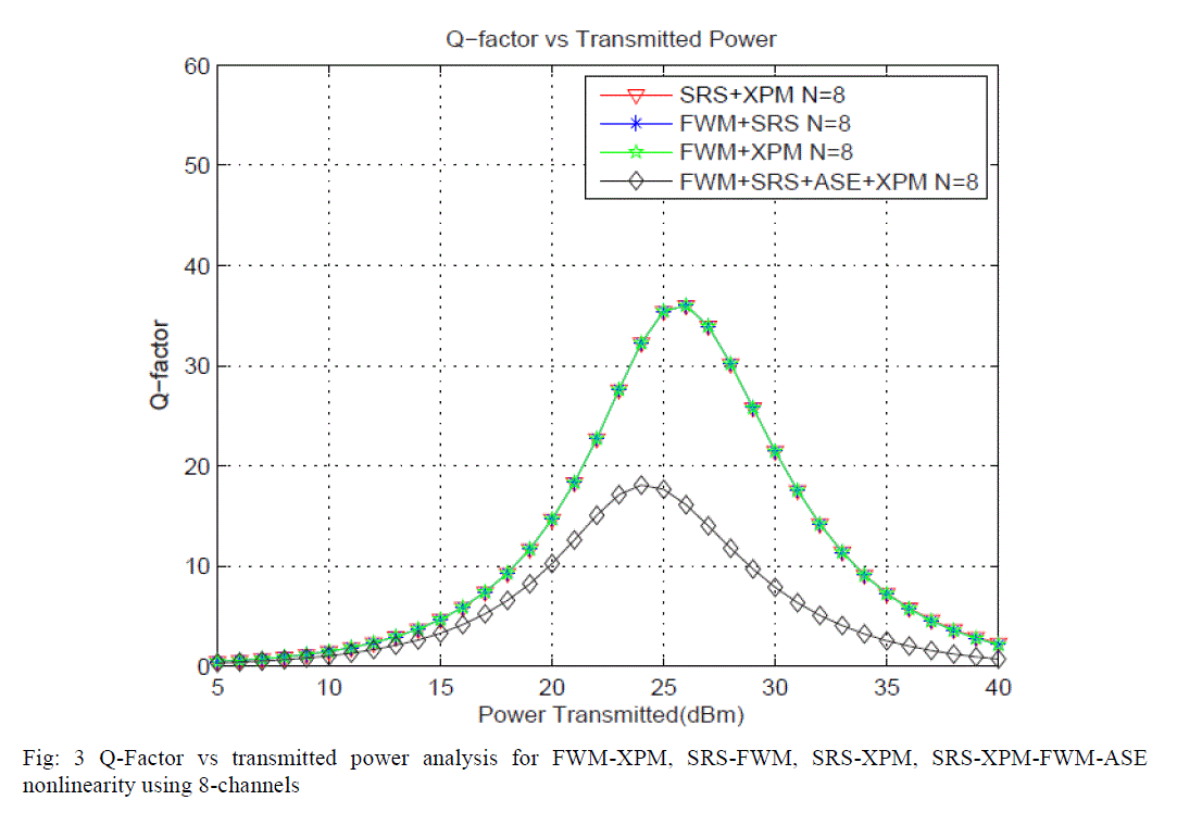
system. Fig: 3 shows the Q-Factor vs transmitted power analysis for FWM-XPM, SRS-FWM, SRS-XPM, SRS-XPMFWM-
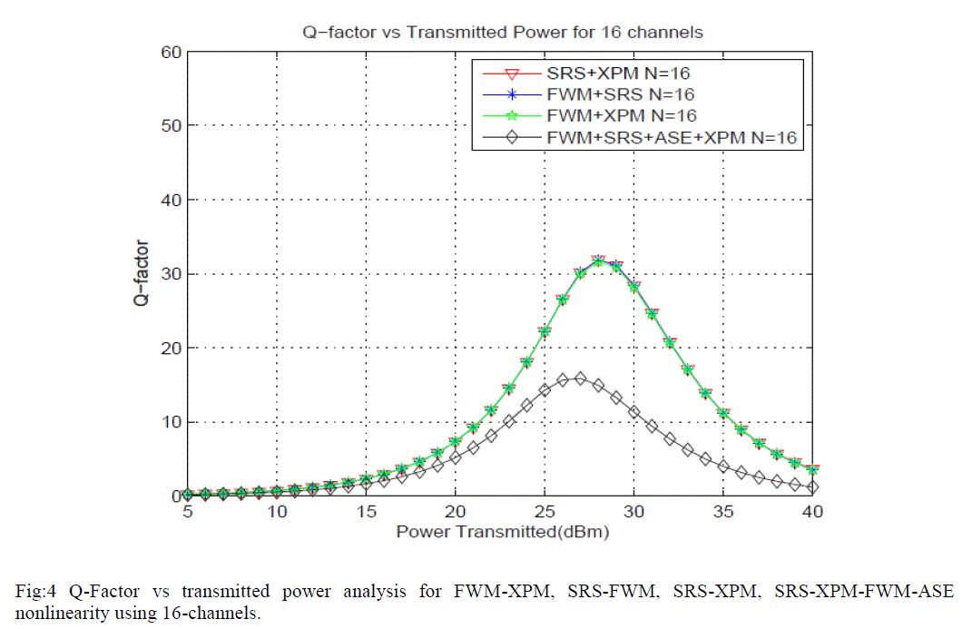
ASE nonlinearity using 8-channels. Fig: 4 shows the Q-Factor vs transmitted power analysis for FWM-XPM,
SRS-FWM, SRS-XPM, SRS-XPM-FWM-ASE nonlinearity using 16-channels. |
 |
 |
CONCLUSION |
| In this paper, non-linear and linear impairments present in fiber that degrade the performance of optical communication
system have been reviewed. As the noise generated by optical amplifier degrades the performance of optical
communication system, placement of amplifier is an important issue in designing all-optical optical communication
system. In this paper result show that the combine effect of the FWM-XPM, SRS-FWM, SRS-XPM, SRS-XPM-FWMASE
nonlinearity based on Q-factor with different number of channels. |
References |
- Mukherjee B. 1992. WDM-based local lightwave networks part-1: Single-hop systems. IEEE Network. 7(5) :12.
- Green P. 2001. Progress in optical networking.IEEE Communication Magazine. 39(1): 54.
- Mukherjee B. 1997. Optical Communication Networks. New York: McGraw Hill. Pp1-10.
- Cavendish D. 2000. Evolution of optical transport technologies: From SONET/SDH to WDM. IEEE Communication Magazine. 38(6):154.
- Acampora A. S. 1994. The scalable lightwave network.IEEE Communication Magazine. 32(12) :36.
- Shen G. and R. S. Tucker. 2007. Translucent optical networks the way forward. IEEE Communication Magazine. 459(2): 48.
- Kaminow I. P., C. R. Doerr, C. Dragone, T. Koch, U. Koren, A. A. M. Saleh, A. J. Kirby, C. M. Ozveren, B. Schofield, R. E. Thomas, R. A. Barry, D. M. Castagnozzi, V. W. S. Chan, B. R. Hemenway, D. Marquis, S. A. Parikh, M. L. Stevens, E. A. Swanson, S. G. Finn, and R. G. Gallager. 1996. A wideband all-optical WDM network. IEEE J. on Selected Areas in Communication. 14(6): 780.
- Alexander S. B., R. S. Bondurant, D. Byrne, V. W. S. Chan, S. G. Finn, R. Galla-gar, B. S. Glance, H. A. Haus, P. Humblet, R. Jain, I. P.Kaminow, M. Karol, R. S. Kennedy, A. Kirby, H. Q. Le, A. A. M. Saleh, B. A. Schofield, J. H. Shapiro, N. K. shankaranarayahan, R. E. Thomas, R. C. Williamson, and R. W. Wilson. 1993. A precompetitive consortium on wideband all-optical networks. Journal of LightwaveTech. 11(5/6): 714.
- Mynbaev D. K. and L. L. Scheiner. 2001. Fiber-optic Communications Technology. Pearson Education Asia.197-199.
- Stolen R. H. and C. Lin. 1978. Self phase modulation in silica optical fibers. Phys. Rev. A-17:1448.
- Chraplyvy A. and J. Stone. 1984. Measurement of crossphase modulation in coherent wavelength division multiplexing using injection laser. Electronics Letters. 20(11): 996.
- Inoue K., K. Nakanishi, K. Oda, and H. Toba. 1994. Crosstalk and power penalty due to fiber four wave mixing in multichannel transmission. Journal of LightwaveTech.12(8) 1423.
- Lin C., W. A. Reed, A. Pearson, and H.T.Shang. 1981. Phase-matching in a minimumchromatic dispersion region of single mode fibers for stimulated four-photon mixing. Opt. Letter. 6: 493.
- Fishman D. A. and J. A. Nagel. 1993. Degradation due to stimulated Brillouin scattering in multigigabitintensity modulated fiber optic systems. Journal of Lightwave Tech. 11(11):1721.
- Ippen E. P. and R. H. Stolen. 1972. Stimulated Brillouin scattering in optical fiber. Appl.Phys. Letters. 21. 539.
- Uesugi N., M. Ikeda, and Y. Sasaki. 1981. Maximum single frequency input power in a long optical fiber determined by stimulated Brillouin scattering. Electronics Letters. 17(2):379.
- D. Cotter. 1982. Transient stimulated Brillouin scattering in long single-mode fiber. Electronics Letters.18: 504.
- Aoki Y., K. Tajima, and I. Mito. 1988. Input power limits of single-mode optical fibers due to stimulated Brillouin scattering in optical communication systems,âÃâ¬Ã Journal of Lightwave Tech., 6(5) : 710.
- Tomita A. 1983. Crosstalk caused by stimulated Raman scattering in single mode wavelength division multiplexed systems. Optics Letters.8(7): 412.
- Ikeda M. 1982. Stimulated Raman amplification characterstics in long span single-mode silica fibers. Optical Communication.39: 148.
- Forghieri F., R. W. Tkach, A. Chraplyvy, and D. Marcuse. 1994. Reduction of four-wave mixing crosstalk in WDM systems using unequally spaced channels. IEEE Photonic Tech. Letters. 6(6): 754.
- G. P. Agrawal. 1997. Fiber-Optic Communication Systems. John Wiley and Sons.pp.141-180
- Shibata N., R. P. Braun, and R. G. Waarts. 1986. Crosstalk due to three-wave mixingprocess in a coherent single mode transmission line. Electronics Letters.22: 675.
- Inoue K. and H. Toba. 1991. Error-rate degradation due to fiber four-wave mixing in fourchannel FSK direct-detection transmission. IEEE Photonic Tech. Letters. 3(1): 77.
- Agrawal, G. P. 2001. Nonlinear Fiber Optics. Academic Press, New York
|