ISSN ONLINE(2319-8753)PRINT(2347-6710)
ISSN ONLINE(2319-8753)PRINT(2347-6710)
N. Pradeep Kumar1, S. Suseel Jai Krishnan2, N. Sakthi Thasan3
|
| Related article at Pubmed, Scholar Google |
Visit for more related articles at International Journal of Innovative Research in Science, Engineering and Technology
Transportation is responsible for approximately 20 per cent of global greenhouse gas emissions such as CO2, NOx and HC which have not been burned completely in the engine. In particular, 55 per cent of globally emitted NOx which is more harmful to the environment than CO2 is produced by the automotive industry alone. Strict emission standards are now in place that set specific limits to the amount of pollutants that can be released into the environment. The widely used measure to reduce NOx emissions in diesel engines is to return part of the exhaust gas to the intake of the engine. This is usually done through via a heat exchanger known as exhaust gas recirculation cooler. However EGR coolers are subject to severe fouling such that their thermal efficiency can drop by as much as 30 per cent within a very short period of time. More importantly, the deposit layer is a blend of particulate matter and sticky heavy hydrocarbons that are very difficult to remove from the heat exchanger surfaces. The present study addresses this problem and provides a review on the effects and R & D activities happening to mitigate fouling of EGR coolers.
Keywords |
| Heat exchanger, Fouling, Exhaust Gas Recirculation, Heat recovery |
INTRODUCTION |
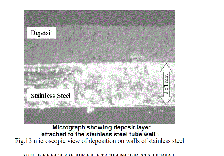
| Exhaust gas recirculation (EGR) has proven to be a useful means of reducing nitrogen oxides (NOx) formation during the combustion process in compression-ignition engines for both conventional and low-temperature combustion modes. Compact heat exchangers are now commonly installed to cool the EGR gases prior to mixing with the fresh air charge, further reducing NOx formation. EGR coolers experience degradation of performance as a result of the build-up of particulate matter (PM) and unburned hydrocarbons (HC) in the gas-side flow paths of the cooler. These form a deposit layer that is less thermally conductive than the stainless steel of the tube enclosing the gas, resulting in lower heat exchanger effectiveness. In the past, EGR coolers were sufficiently large and the NOx targets sufficiently high that the cooler fouling process was of less importance. Now, smaller more efficient coolers are beneficial from both a cost and a packaging standpoint. However, maintaining the EGR cooler at a high level of performance has become a significant issue in terms of achieving compliance with increasingly stringent NOx regulations. There is little data in the literature to describe the thermal properties of EGR cooler deposits. Models of the fouling process and its effect on cooler performance require reasonably accurate data on the thermal properties of the layer and how they change with engine conditions and with time. Successful modelling of the fouling process represents the most efficient means of designing future EGR systems to reduce the impacts of fouling. |
II. EFFECT OF SPIRAL GROOVES IN CORRUGATED COOLERS |
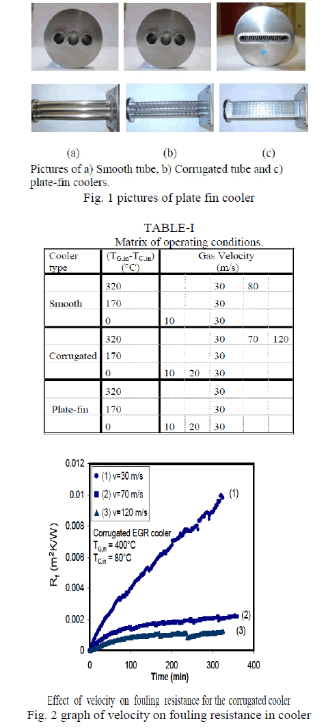
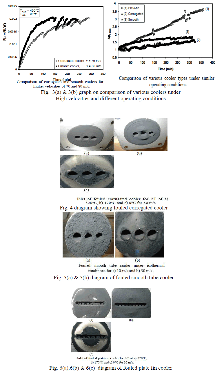
| The quantitative fouling results under isothermal and thermo-phoretic conditions facilitated a better understanding of soot deposition in EGR coolers with different geometries. Regardless of other technical considerations, increased gas velocity, low temperature gradient between inlet gas and coolant, and complex geometrical texture that would increase local heat transfer area are shown to reduce particulate fouling. Deposition under isothermal conditions is marginal as long as the surface is smooth and gas velocity is not too low. For the plate-fin cooler with extended surfaces, however, this may become appreciable due to impaction of soot particles on to the surface. The presence of spiral grooves in corrugated cooler initially helped to increase local shear forces. Nevertheless their advantages deteriorated as soon as the grooves were fouled by soot particles [1, 14] |
 |
 |
III. EFFECT OF REPLACEMENT OF SURROGATE TUBE SAMPLES FOR EGR |
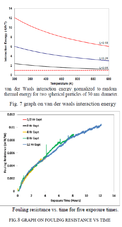
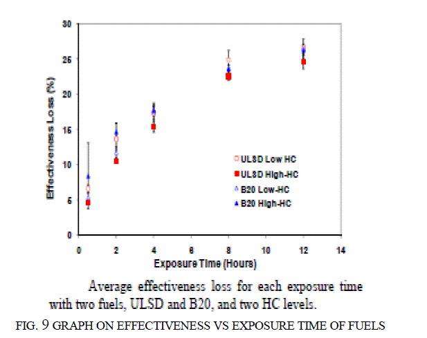
| Use of a surrogate tube sampler in place of an actual EGR cooler allowed for independent and repeatable control of key factors impacting EGR cooler fouling. The tubes are also easily removed for post-test analysis. The heat transfer effectiveness loss of the surrogate tubes appeared to be reaching plateau. Higher HC levels initially resulted in greater deposit mass accumulation and increased deposit density but at later time intervals the deposit mass gain and density was similar to lower HC experiments. Neither various "anti-stick" tube coatings/surface treatments or B20 fuel versus ULSD fuel appeared to have any significant impact on effectiveness loss or deposit mass gain for these experiments. The soot deposits in EGR coolers are actually PM aggregates which form a highly porous deposit layer, with thermal conductivities in the range of 0.04 W/mK (similar to expanded polystyrene foam insulation). The resulting increase in deposit layer temperature as this porous PM layer builds weakens the van der Waals force which are understood to be the primary soot adherence force. The weakened attraction along with decreased shear strength of the PM aggregates in the higher temperature outer extremities of the deposit layer may explain the asymptotic behaviour of the loss of heat transfer effectiveness. [1] |
 |
 |
IV.PROPERTY VARIATIONS DUE TO FOULING DEPOSITIONS |
| Mass-based deposition efficiency: Conditions favouring condensation of vapour components, i.e. low coolant and gas temperatures, enable diffusiophoresis to act. This results in high mass-based deposition efficiencies showing that diffusiophoresis has a major contribution to EGR cooler fouling and needs to be considered besides thermophoresis. Size-dependent deposition efficiency: Turbulent eddy diffusion and temperature effects increase deposition efficiencies especially for particles smaller than 50 nm. Effects inside the cooled section of the cooler are negligible. The different mechanisms that are involved in the soot deposition within heat exchangers add to the formation of a soot layer. All of the mechanisms considered act most effective at the cooler inlet where geometry and temperature conditions are most favourable.To improve EGR cooler performance, wash out effects due to water condensation should be specifically induced and conditions under which no water, but large amounts of hydrocarbons condense, should strictly be avoided. Further experiments with different aerosol composition are still needed to describe the processes happening in the EGR coolers in greater detail. [2] |
 |
V. MECHANISMS INVOLVED IN SOOT PARTICLE DEPOSITION |
| Fouling of EGR coolers introduces a very significant uncertainty into the design and operation of this equipment. Different fouling mechanisms such as particulate, sedimentation due to gravity and spinning and solidification may also be responsible. However the contribution of each of these individual fouling mechanisms is still unknown. Several mitigation techniques have been proposed to minimize fouling of EGR coolers, but so far none of them is capable of preventing fouling or keeping it at a reasonable level. Increasing the gas velocity in the EGR coolers, preventing excessive cooling of the exhaust gasses across the cooler especially at the beginning of operation and usage of DOC together with DPF seem to be promising ways of reducing particulate fouling. However, the applicability of such methods still needs to be investigated. [3] |
VI. DEVELOPMENT OF EGR COOLER FOULING MODEL |
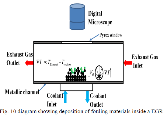
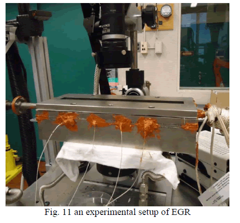
| Cooled EGR is an increasingly important NOx reduction technology for current and future diesel engines. Higher EGR flow rates and cooling levels required by future emissions regulations exacerbate fouling, or the deposition of soot and HC exhaust constituents, degrading EGR cooler performance. An EGR cooler fouling model is developed and correlated to shorter term controlled EGR cooler fouling experiments. Longer term EGR cooler fouling experiments appear to require a “removal mechanism” to achieve correlation. A deposit visualization rig has been developed and is running experiments to observe these suspected removal mechanisms in real time. Water condensation and large particle bombardment appear to be important removal mechanisms. Other removal mechanisms are under investigation. [4] |
VII. VISUALIZATION OF DEPOSITION AND REMOVAL MECHANISMS |
| A methodology for collecting deposits in surrogate EGR cooler tubes has been demonstrated. Measurements of the thermal properties of the deposit layer have been successfully accomplished. Average results for a limited number of samples has shown that the thermal conductivity of EGR cooler deposits with low levels of condensed HCs are quite low; measured values average 0.041 W/mK. This result is comparable to the thermal conductivity of materials known as effective insulators. More studies are needed to characterize the range of variation in deposit thermal properties that can be expected in practice and to lend understanding to the connections between operational. [5] Cooled EGR is an increasingly important NOx reduction technology for current and future diesel engines. Higher EGR flow rates and cooling levels required by future emissions regulations exacerbate fouling, or the deposition of soot and HC exhaust constituents, degrading EGR cooler performance. An EGR cooler fouling model is developed and correlated to shorter term controlled EGR cooler fouling experiments. Longer term EGR cooler fouling experiments appear to require a “removal mechanism” to achieve correlation. A deposit visualization rig has been developed and is running experiments to observe these suspected removal mechanisms in real time. Water condensation and large particle bombardment appear to be important removal mechanisms. Other removal mechanisms are under investigation. [6, 7] |
 |
 |
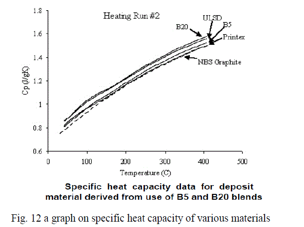
| This paper reports results of a study of fundamental aspects of EGR cooler fouling. An apparatus and procedure were developed to allow surrogate EGR cooler tubes to be exposed to diesel engine exhaust under controlled conditions. The resulting fouled tubes were removed and analysed. Volatile and non-volatile deposit mass was measured for each tube. Thermal diffusivity of the deposited soot cake was measured by milling a window into the tube and using the Xenon flash lamp method. The heat capacity of the deposit was measured at temperatures up to 430°C and was slightly higher than graphite, presumably due to the presence of hydrocarbons. These measurements were combined to allow calculation of the deposit thermal conductivity, which was determined to be 0.041 W/mK, only ~1.5 times that of air and much lower than the 304 stainless steel tube (14.7 W/mK). The main determinant of the deposit thermal conductivity is density, which was measured to be just 2% that of the density of the primary soot particles (or 98% porous). The deposit layer thermal resistance was calculated and compared with estimates of the thermal resistance calculated from gas temperature data during the experiment. The deposit properties were also used to further analyse the temperature data collected during the experiment. The fuels used were ULSD, B5, B20. [8] |
 |
 |
VIII. EFFECT OF HEAT EXCHANGER MATERIAL |
| This study is conducted in an effort to better understand and improve the performance of thermoelectric heat recovery systems for automotive use. For this purpose an experimental investigation of thermo electrics in contact with clean and fouled heat exchangers of different materials is performed. The thermoelectric devices are tested on a bench-scale thermoelectric heat recovery apparatus that simulates automotive exhaust. It is observed that for higher exhaust gas flow rates, thermoelectric power output increases from 2 to 3.8W while overall system efficiency decreases from 0.95% to 0.6%. Degradation of the effectiveness of the EGR-type heat exchangers over a period of driving is also simulated by exposing the heat exchangers to diesel engine exhaust under thermophoretic conditions to form a deposit layer. For the fouled EGR-type heat exchangers, power output and system efficiency is observed to be 5–10% lower for all conditions tested. Clean and fouled aluminium and stainless steel EGR-style heat exchangers have been tested on a bench-scale thermoelectric apparatus to simulate automotive exhaust heat recovery. The thermoelectric devices were tested with different hot-side stainless steel and aluminium EGR-type heat exchangers for various heated exhaust gas flow rates ranging from 40 to 150 slpm, exhaust gas temperatures of 2400C and 2800C, and coolant side temperatures of400C and 800C simulating possible temperature ranges downstream of the engine manifold and engine coolant. From analysis of the results it was observed that the recovered electrical power of the thermoelectric devices can be increased by elevating the temperature of the exhaust gas, decreasing the temperature of the coolant, or by increasing the flow rate of the heated gas. System Efficiency increases with an increase in electrical power when the bulk temperature gradient increases. System efficiency decreases with an increase in electrical power when the exhaust gas flow rate is increased. A large effect of heat exchanger material was also documented in this study. This is thought to be a combined effect of the higher thermal conductivity of aluminium compared to stainless steel and the excessive wall thickness of the heat exchangers used in this study. A more optimally designed heat exchanger would likely be less sensitive to heat exchanger material. Heat exchangers fouled with diesel exhaust experience degradation in performance of 5–10% compared to an unfouled heat exchanger of the same material. [9] |
IX. EFFECT OF HEAT TRANSFER AND SOOT DEPOSITION CHARACTERISTICS |
| Controlled soot deposition tests were performed on a series of generic single-tube and three-tube EGR cooling devices that were exposed to exhaust gas for different periods of times in the diesel exhaust test facility to investigate the timedependent heat transfer and pressure drop characteristics of these devices. A non-destructive technique was developed to characterize the three dimensional soot layers that occurred in the EGR cooling devices using the neutron radiography test facility of the McMaster Nuclear Reactor. The results showed that the deposited soot layer in the single-tube devices was much larger for the higher flow rate which corresponded to turbulent flow, particularly in the entrance region. The thickness of the deposited soot in the entrance region of the tube was much larger than the remainder of the tube, and appeared to restrict the flow area by up to 75% over a length of 4 tube diameters. The variation in the deposited soot thickness throughout the rest of the tube is similar in magnitude to the layer itself indicating that the soot layer in the tube was three-dimensional. The results also showed that the profiles of the deposited soot had a wave-like structure in all cases. The thermal effectiveness of the devices decreased from approximately 82% to % over 5 hours for the laminar flow test case and from 70% to 35% for the turbulent flow test. The pressure drop across these devices increased by up to 320% during the 5 hours of testing. Measurements were also performed using three-tube EGR cooling devices with 45° and 60° expansion angle inlet headers exposed to diesel exhaust for 3 hours. The soot deposition was more evenly distributed in the tube bundle with the 60° expansion angle inlet header suggesting that the flow may be more evenly distributed in this device. There was more soot deposited in the centre tube than outer tubes in the three-tube bundle with the 45° expansion angle inlet header suggesting that the flow was not evenly distributed. The thermal effectiveness in both cooling devices decreased during the 3 hours of testing, but the change in the effectiveness was larger for the device with the 45° expansion angle inlet header. The pressure change in the exhaust gas across the cooling devices increased more rapidly for the device with the 45° expansion inlet header, reaching a nearly constant value of nearly 5 times the initial value after 3 hours. [10] |
X. CONCLUSION |
| EGR is a very useful technique for reducing the NOx emission. EGR displaces oxygen in the intake air and dilute the intake charge by exhaust gas recirculated to the combustion chamber. Recirculated exhaust gas lower the oxygen concentration in combustion chamber and increase the specific heat of the intake air mixture, which results in lower flame temperatures. It was observed that 15% EGR rate is found to be effective to reduce NOx emission substantially without deteriorating engine performance in terms of thermal efficiency, BSFC and emissions. Thus, it can be concluded that higher rate of EGR can be applied at lower loads and lower rate of EGR can be applied at higher load. EGR can be applied to diesel engine fueled with diesel oil, biodiesel, LPG, hydrogen, etc without sacrificing its efficiency and fuel economy and NOx reduction can thus be achieved The literature survey presented in this paper highlights various aspects related to the operation of EGR coolers in diesel engines which are installed to achieve compliance with emissions regulations. In particular, fouling of EGR coolers introduces a very significant uncertainty into the design and operation of this equipment. Different fouling mechanisms such as particulate sedimentation due to gravity and spinning and solidification may also be responsible. However the contribution of each of these individual fouling mechanisms is still unknown. Several mitigation techniques have been proposed to minimize fouling of EGR coolers, but so far one of them is capable of preventing fouling or keeping it at a reasonable level. Increasing the gas velocity in the EGR coolers, preventing excessive cooling of the exhaust gases across the cooler especially at the beginning of operation and usage of DOC together with DPF seem to be promising ways of reducing particulate fouling. However the applicability of such methods still needs to be investigated. |
References |
|