The wind energy sources are characterized by irregularity and unpredictability. It is very important to make DC-link voltage constant for doubly fed induction generator wind energy conversion system. The DC-link provides an extra spinning reserve facility for the wind system, which can be used for sink or source of active power. This paper presents the DC-link voltage fluctuation for a back to back pulse width modulation converter in doubly fed induction generator for wind turbine systems. The effects of load variation on DC link electrolytic capacitor voltage of DFIG based wind energy conversion system (WECS).As DFIG based WECS utilize low power converter, so there is a need to explore the effects of DC-link voltage. For this there are two cases (i) At fixed speed effect of load variation on dc link voltage Vdc (ii) At variable speed effect of load variation on dc link voltage Vdc. These cases are compared with healthy fixed and variable DFIG wind energy conversion system. All these scenarios have been simulated with the help of the simulation program using MATLAB and its inbuilt components provided in SIMULINK library
Keywords |
| Rotor Side Converter, Stator Side Converter, Pulse Width Modulation, Wound Rotor Induction
Generator. |
INTRODUCTION |
| Over the last twenty years, renewable energy sources have been attracting great attention due to the cost increase,
limited Reserves and adverse environmental impact of fossil fuels. In the meantime, technological Advancements, cost
reduction, and Governmental incentives have made us to utilize more renewable energy sources for generation of
electricity [1]. Wind energy is used for hundreds of Years for milling grains, pumping water, and sailing the seas. The
use of windmills to generate electricity can be traced back to the late nineteenth century with the development of a
12kW dc windmill generator. It is, however, only since the 1980s that the technology has become sufficiently mature to
produce electricity efficiently and reliably. Over the past two decades, a variety of wind power technologies have been
developed, which have improved the conversion efficiency and reduced the costs for wind energy production. The size
of wind turbine has increased from a few kilowatts to several megawatts each. In addition to on-land installation, larger
wind turbines have been pushed to offshore location to harvest more energy and reduce their impact on land use and
landscape [2]. With the increased penetration level of wind power in the power system, grid utilities want wind turbine
generator system to behave like a conventional synchronous generator in terms of real and reactive power settings [3].
In other words, wind turbines have to contribute not only to active power generation but also to the reactive power.
Hence, wind turbines should have extended reactive power capability not only during voltage dips but also in steady
state operation [4]. Although, the DFIG wind turbines are able to control active and reactive power independently of
one another by virtue of ac/dc/ac power electronic converter present on it, The grid side inverter reactive power
capability can be taken into consideration, but in commercial system, this converter usually works with unity power
factor, i.e. zero reactive power, so the total reactive power capability of the generator is equal to the stator reactive
power capability [5, 6]. In [7], a rotor position Phase-Locked Loop (PLL) is used which acquires the rotor position and
rotor speed simultaneously for the implementation of the decoupled P-Q control in the DFIG. |
WIND TURBINE |
| Wind energy comes from wind turbine blades and then transferred to a gear box (to match the high speed generator
with low speed turbine blades) & the rotor hub to provide mechanical energy to the shaft. The shaft drives the generator
to converts the mechanical energy in to electrical energy. The power of an air mass flowing at speed V through an area
A can be calculated by |
 (1) (1) |
| Where, P is power in watts (W),ρ is the air density in kilograms per cubic meter (kg/m3),A is the swept rotor area in
square meter (m2),V is the wind speed in meter per second (m/s).But the turbine model is based on the power captured
by the blade &converted into mechanical energy. |
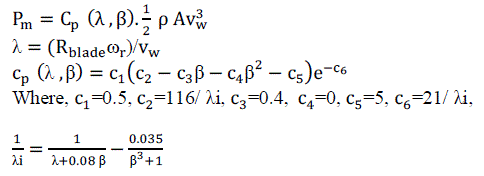 (2),(3),(4) (2),(3),(4) |
| Where PM is the mechanical power output power in watts & Cp is the power coefficient of the blade which depends on
the tip speed ratio (λ) & blade pitch angle (β).CP decides how much energy can be captured by wind turbine system.
To get maximum Cp, one has blade pitch angle (β=0) and tip speed ratio (λ=8).in this paper wind turbine model, for
different wind speeds and fixed pitch angle at β=0. |
DFIG WIND SYSTEM AND EQUATIONS |
| The DFIG is the same as the WRIG system except that variable resistance in the rotor circuit is replaced by a gridconnected
power converter system &there is no need for the soft starter or reactive power compensation .and also the
power factor is adjusted by power converter itself. The use of convertors also allows bidirectional power flow in the
rotor circuit & increase the speed range of the generator (extended generator speed range ±30%), also improved the
overall power conversion efficiency. The DFIG typically operates about 30% above & below synchronous speed,
sufficient for most wind speed conditions. It also enables generator side active power control & grid side active power
control. In the DFIG model of wind energy the active and reactive power are controlled independently. The wind
turbine drives DFIG wind system consists of a WRIG (wound rotor induction generator) and an AC/DC/AC IGBT
based PWM converter (back to back converter with capacitor dc link) or we can say that two levels IGBT voltage
source converter (VSC) system in a back to back configuration is normally used. Since both stator and rotor can feed
power to gird, the generator is known as doubly fed induction generator (DFIG).It has two main parts ,the rotor side
converter control (RSC), which controls the torque or active/reactive power of the generator and, grid side converter
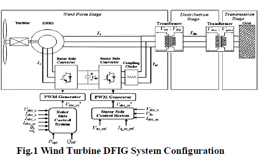
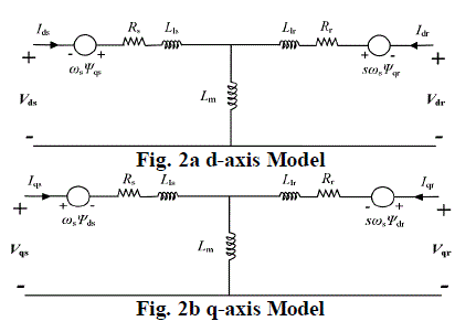
controls (GSC), which controls the DC link voltage and its AC-side reactive power. An equivalent circuit of DFIG
wind system shown in Fig.1 and Fig. 2a, 2b and relation equations to voltage V, current I, flux linkage Ψ, and
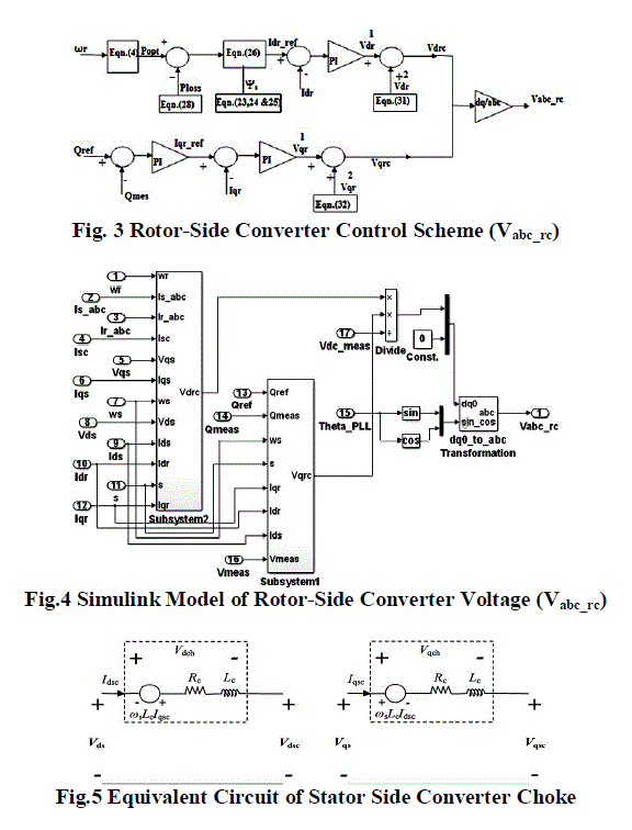
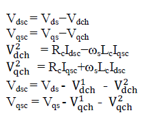
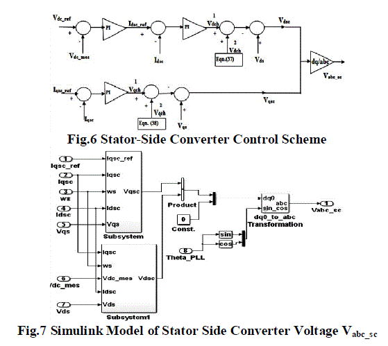
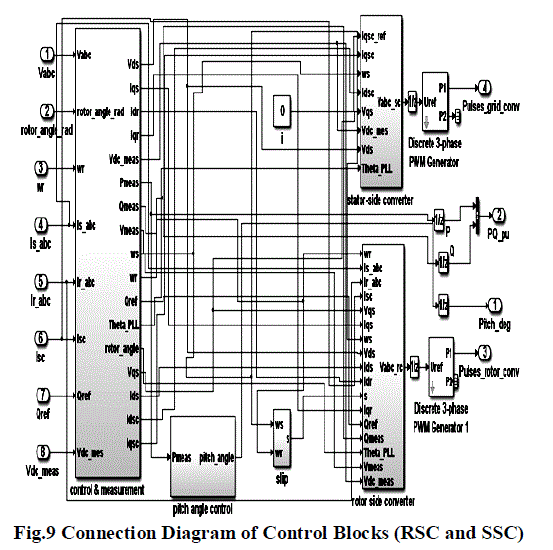
electromagnetic torque Te are as fallows. Fig. 3 & 4 shows the rotor-side converter control of voltage block diagram
and simulink model respectively and Fig. 5 shows the equivalent circuit of stator-side converter choke. |
 |
| d-q Reference frame model |
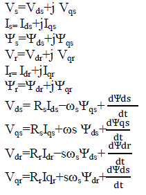
| Voltage equations |
 |
 |
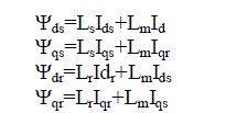 |
| Electromagnetic torque equation |
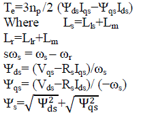 |
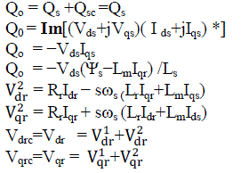
| The subscripts r, s and d, q represents the rotor & stator, d-axis, q- axis components respectively, Te is electromagnetic
torque, Lm & J are generator mutual inductance, and the inertia coefficient, respectively. |
 |
| Where Isc, Rc and F are stator-side converter current & choke resistance, friction factor. Popt, P_ref and Ploss are desired
optimal output active power, reference active power and system power loss. |
 |
 |
 |
 |
 |
 |
SIMULINK MODELLING OF DFIG WIND SYSTEM |
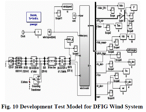
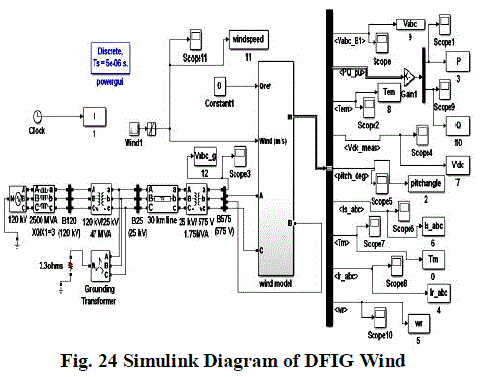
| Fig. 10 shows DFIG wind model simulation in MATLAB/SIM-POWER SIMULINK. The three phase programmable
source is generating power at 120 kV, which is stepped down to 25 kV by the two winding transformer and then
transmitted by the 30 km long transmission line for further stepping down the voltage level to the 575 V at point of
common coupling between grid and DFIG wind energy conversion system . The DFIG wind energy conversion system
is generating power of 1.5 MW. |
 |
| In this, the wind turbine uses a doubly-fed induction generator (DFIG), which consists of a wound rotor induction
generator and an AC/DC/AC IGBT-based PWM converter. The dc voltage is applied to IGBT/Diode‘s of two level
inverter. The pulse width modulation technique has been used in this inverter, in order to achieve higher accuracy , the
carrier frequency or switching frequency is 1620 Hz, discrete sample time is, Ts =5 microseconds. The stator winding
is connected directly to the 60 Hz grid while the rotor is fed at variable frequency through the AC/DC/AC converter.
The DFIG wind system allows extracting maximum energy from the wind for low wind speeds by optimizing the
turbine speed, while minimizing mechanical stresses on the turbine during the gusts of wind. In this, wind speed is
maintained constant at 15 m/s. The DC voltage is regulated at 1200 V and reactive power is kept at 0 Mvar. When we
double click on wind model block then it shows a generator, a converter, a turbine, & a drive train and the control
system block. |
(A) DFIG WORKING ANALYSIS AT FIXED SPEED |
| DC link Voltage, Grid Side voltage without and with Filter (Vdc, Vabc_g, Vabc) |
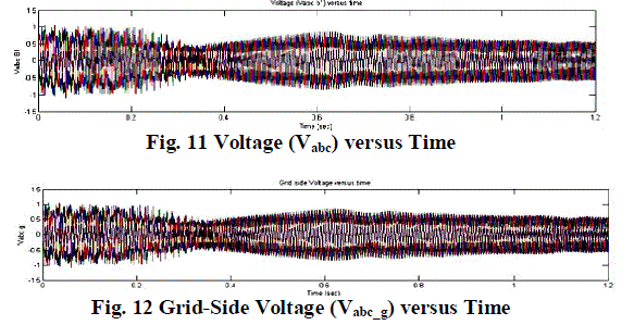
| Fig 11, Fig 12 & Fig 13 shows the grid voltage with and without filter and dc link voltage under the fixed wind speed.
It can be seen that the voltage vabc, vabc_g has little-bit variation during starting up to 0.4 sec and after that it will become
stable & maintained constant at 0.6 pu, the dc link voltage Vdc almost constant during simulation time (1.2 sec). |
 |
 |
Stator and Rotor Current of DFIG |
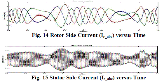
| Fig 14 & Fig.15 shows the stator-side and rotor-side current of DFIG wind system under fixed wind speed. It can be
seen that rotor current of DFIG system has variation between 0.5 to 0.6 sec and between 0.9 to 1.1 sec and beside these
point it is almost constant which is almost 1 pu and little above but the stator current has less variation between 0.5 to
0.6 sec and between 0.9 to 1.1 sec as compare to rotor current beside these points it is almost stable. |
 |
Active and Reactive Power Variation |
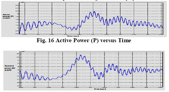
| Fig. 16 And 17 shows the active and reactive power of DFIG wind energy system under fixed wind speed. It can be
seen that the active power varies around the required 1.5 MW, the average variation in the real power and reactive
power is almost negligible. Fig. 17 shows that during period 0.6 to 0.7 sec it is supplying reactive demanded by load
while during period 0.7 to 0.75 sec the reactive power is being absorbed by system. |
 |
| Variation of Electro-Mechanical Torque Developed Torque (Tem and Tm) |
| Fig. 18 shows the Electro-Mechanical Torque (Tem) under the fixed wind speed. It can be seen that the torque is
Pulsating but the torque during starting of the simulation are very low, while developed torque (Tm) are smooth. |
 |
 |
| (B) DFIG SYSTEM PARAMETER ANALYSIS AT VARIABLE SPEED |
 |
| ENERGY CONVERSION SYSTEM AT VARIABLE SPEED |
| DC link Voltage, Grid Side voltage without and with Filter (Vdc, Vabc_g, Vabc) |
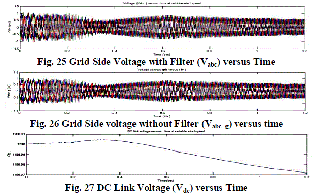
| Fig. 24, 25 and Fig. 26 shows the Grid Side voltage without and with Filter, DC link Voltage, (Vabc, Vabc_g, Vdc). It can
be seen that the variation of voltage Vabc and Vabc_g are very much with respect time in comparison to fixed wind speed
system. But the Vdc developed almost constant. The dc link voltage has a little bit variation. In case with filter the
becomes quite smooth. |
 |
| Stator and Rotor Current of DFIG |
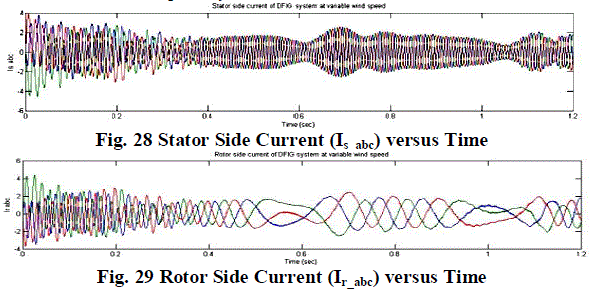
| Fig. 28 and 28 shows the stator and rotor current of DFIG wind system at variable wind speed. It can be seen that rotor
current of DFIG system has variation between 0.5 to 0.6 sec and between 0.9 to 1.1 sec and beside these point it is
almost constant, which is almost 1 pu but the stator current has less variation between 0.5 to 0.6 sec and between 0.9 to 1.1 sec as compared to rotor current, beside these points it is almost stable. But the variations in currents with respect
time are more in comparison to fixed wind speed system. |
 |
| Active and Reactive Power variation |
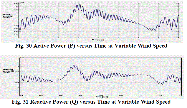
| Fig. 30 and 31 shows the active and reactive power of DFIG wind energy system under variable wind speed. It can be
seen that the both active power and reactive power has little variation as compare to fixed wind speed system. Fig. 31
shows some time it gives power and some time it absorbs the power (reactive power with respect time curve).Compare
to fixed speed the variable speed system working is quite better. |
 |
| Variation of Electro-Mechanical Torque and Developed Torque (Tem and Tm) |
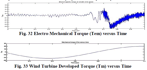
| Fig. 32 & 33 shows the Electro-Mechanical Torque (Tem) & developed torque(Tm). Tem has little bit variation in
comparison to the fixed speed and after 0.7 sec. it is varying. But developed torques’s Tm are smooth. |
 |
| CASE:-1 SIMULATION RESULTS WHEN THE FIXED WIND SPEED IS PASSED ON DFIG |
| (C) AT FIXED SPEED EFFECT ON DC LINK VOLTAGE Vdc |
| Effect on DC Link Voltage when the load is 1.5 Mw Load |
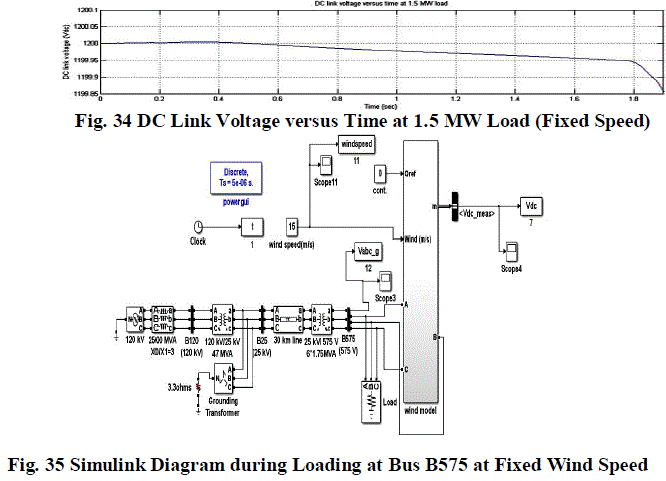
| The developed simulink model in Figure No. 35 was simulated for 2 sec at the load of 1.5 MW at the fixed speed of 15
m/s during simulation. it can seen in Fig. 34 the dc link voltage (Vdc ) up to 0.43 sec it is almost constant and after 0.43
sec there is variation the dc link voltage of only 0.05 volts up to 1.83 sec.The value of dc link voltage is 1199.95 volt at
that point. Practically the Vdc developed can be considered constant. |
 |
| Effect on DC Link Voltage when the load is 1 Mw Load |
| Fig. 36 shows the DC link voltage (Vdc) at 1MW load. The developed simulink model was simulated for 2 sec at the
load of 1 MW at the fixed of 15 m/s during simulation .it can seen that the dc link voltage up to 0.43 sec it is almost
constant and after 0.43 sec there is variation the dc link voltage of only 0.05 volts but it is decreases after 1.85 sec. The
value of dc link voltage is 1199.95 volt, which can practically very much closure to 1200 V. |
 |
| Effect on DC Link Voltage when the load is 0.5 Mw Load |
|
Fig. 37 shows the DC link voltage (Vdc) at 0.5MW load under fixed wind speed. The developed simulink model was
simulated for 2 sec at the load of 0.5 MW at the fixed of 15 m/s during simulation .it can seen that the dc link voltage
up to 0.43 sec it is almost constant and after 0.43 sec there is variation the dc link voltage of only 0.05 volts but it is
decreases after 1.87 sec. The value of dc link voltage is 1199.95 volt. Which can practically very much closure to 1200
Volt. |
 |
| CASE:-2 SIMULATION RESULTS WHEN THE VARIABLE WIND SPEED IS PASSED ON DFIG |
 |
| (D) AT VARIABLE SPEED EFFECT ON DC LINK VOLTAGE Vdc |
| Effect on Dc Link Voltage at 1.5 MW Load |
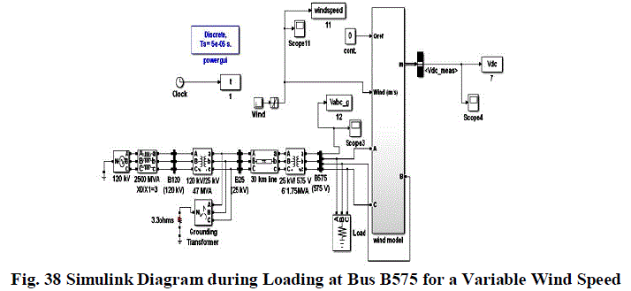
| The developed simulink model in Figure No.38 was simulated for 2 sec in the Fig. 39 the DC link voltage (Vdc) at
1.5MW load under variable wind speed i.e. 12 to 15 m/s was simulated at 1.5 MW, during simulation .It can seen that
the dc link voltage up to 0.58 sec it is almost constant .However after 0.58 sec there is variation the dc link voltage of
only 0.05 volts but it is decreases after 1.79 sec. up to 1.83. The value of dc link voltage is 1199.95 volt at that point. |
 |
| Effect on Dc Link Voltage at 1.0 MW Load |
| Fig. 40shows the DC link voltages (Vdc) at 1.0 MW load under variable wind speed. The developed simulink model
was simulated for 2 sec at the load of 1.0 MW at the variable wind speed from 12 to 15 m/s during simulation .it can
seen that the dc link voltage up to 0.58 sec it is almost constant and after 0.58 sec there is variation the dc link voltage
of only 0.05 volts but it is decreases after 1.854 sec. The value of dc link voltage is 1199.95 volt. |
 |
| Effect on Dc Link Voltage at 0.5 MW Load |
| Fig. 41 shows the DC link voltage (Vdc) at 0.5MW load under variable wind speed. The developed simulink model
was simulated for 2 sec at the load of 0.5 MW at the variable wind speed from 12 to 15 m/s during simulation .it can
seen that the dc link voltage up to 0.58 sec it is almost constant and after 0.58 sec there is variation the dc link voltage
of only 0.001 volts but it is decreases after 1.675 sec. The value of dc link voltage is 1199.999 volt at that point. So,
here it can say that fix speed wind system are good for dc link voltage to connect the load at grid end. |
 |
CONCLUSION |
| A DFIG wind system have been modelled and simulated in MATLAB software. It can be seen that when DFIG wind
system is operated without load at both fixed and variable speed the DC-link voltage are almost constant. But when the
DFIG wind system are loaded with different load at grid-side for fixed wind speed ,then it can be seen that as the load
of the system is decreases the DC-link voltage remains constant more time than the higher load. However in case
increase in the load there in very nominal effect on the load link voltage profile. But when the DFIG wind system are
loaded with varying load at grid system for variable wind speed, it can be seen that when the 1.5MW load is applied
DC-link voltage is almost constant 1.79 s.& for 1MW load it is almost constant up to 1.825s.,and for 0.5 MW load it is
almost constant up to 1.63s.,it is observes that for variable wind speed system the dc-link voltage is very much constant
in compare with fixed speed system .But the main difference between variable and fixed wind speed system is that
when the load goes lower beyond certain level the dc link voltage stability gets affected while in fix speed there is no
effect on the stability. So it is here concluded that whenever DFIG system is operated there should a minimum load on
the system for getting constant DC link voltage. |
References |
- Renewable Energy Policy Network for the 21st Century (REN21), available at www.ren21.net.
- T.Burton, D.Sharpe, N.Jenkins and E.Bossanyi, Wind energy handbook, Wiley, 2001.
- Stephan Engelhardt, IstvanErlich, Christian Feltes, JÃâèorgKretschmann, and FekaduShewarega, âÃâ¬ÃÅReactive Power Capability of Wind Turbines Based on Doubly Fed Induction Generator,âÃâ¬Ã IEEE Trans. on Energy Conversion, Vol. 26, No. 1, pp. 364-372, March 2011.
- Mustafa KayikcÃâøi and Jovica V. MilanoviÃâôc, âÃâ¬ÃÅReactive Power Control Strategies for DFIG-Based Plants,âÃâ¬Ã IEEE Trans. on Energy Conversion, Vol. 22, No. 2, pp. 389-396, June 2007.
- Torsten Lund, Poul Sorenson and Jarle Eek, âÃâ¬ÃÅReactive Power Capability of a Wind Turbine with Doubly Fed Induction Generator,âÃâ¬Ã Wind Energy, vol. 10, iss. 4, pp.379-394, Apr. 2007.
- D. Santos-Martin, S. Arnaltes, and J.L. Rodriguez-Amenedo, âÃâ¬ÃÅReactive power capability of doubly fed asynchronous generators,âÃâ¬Ã Electric Power Systems Research, vol.78, pp.1837-1840, 2008.
- BakariMwinyiwiwa, Yongzheng Zhang, Baike Shen, and Boon-Teck Ooi, âÃâ¬ÃÅRotor Position Phase-Locked Loop for Decoupled P-Q Control of DFIG for Wind Power Generation,âÃâ¬Ã IEEE Transactions on Energy Conversion, vol. 24, no. 3, pp. 758-765, Sept. 2009.
- Cortajarena J.A., De Marcos J., Alvarez P., Vicandi F.J. Alkorta P., âÃâ¬ÃÅStart up and control of a DFIG wind turbine test rigâÃâ¬Ã , IECON 2011 - 37thAnnual Conference on IEEE Industrial Electronics Society, Nov 2011.
- R. R. Peters, D. Muthumuni, T. Bartel, H. Salehfar, and M. Mann, âÃâ¬ÃÅDynamic Model Development of a Fixed Speed Stall Control Wind Turbine at Start-UpâÃâ¬ÃÂ, Power Engineering Society General Meeting, IEEE, 2006.
- Ankit Gupta, S.N.Singh, Dheeraj K. Khatod, âÃâ¬ÃÅModeling and Simulation of Doubly Fed Induction Generator Coupled with Wind Turbine âÃâ¬ÃâAn OverviewâÃâ¬ÃÂ, JEC&AS, Vol. 2, No.8, Aug. 2013.
- Jun Yao,Hui Li, Yong Liao, and ZheChen,âÃâ¬ÃÂAn Improved Control Strategy of Limiting the Dc-Link Voltage Fluctuation for a Doubly Fed Induction GenerationâÃâ¬ÃÂ,IEEE Transactions on Power Electronics,Vol.23,No.3,May 2008.
- S. N. Singh, Jacob ÃÆÃËstergaard, and Bharat Singh, âÃâ¬ÃÅReactive Power Capability of Unified DFIG for Wind Power GenerationâÃâ¬ÃÂ, IEEE, 2010.
|